
Part Number:
Quantity:
Price per Unit (in USD):
Total Amt:
Log in to myMicrochip to access tools and benefits. Sign up in just one minute.
Maximize Your Experience: Reap the Personalized Advantages by Completing Your Profile to Its Fullest! Update Here
Stay in the loop with the latest from Microchip! Update your profile while you are at it. Update Here
Complete your profile to access more resources.Update Here!
true
Live Chat
Need Help?
Privacy Policy {"Stage_EswLiveAgentDevName":"EmbeddedServiceLiveAgent_Parent04I3l000000CaZuEAK_184c4646b8d","Stage_SalesforceOrgId":"00DWD000003lT85","Agent_Available_Header":"No problem. Chat with our engineering experts or schedule a call that's convenient for you.","Prod_SalesforceOrgId":"00Do0000000KAkK","Stage_SalesForcePath":"https://microchip--mcuat.sandbox.my.salesforce.com","Prod_EswLiveAgentDevName":"EmbeddedServiceLiveAgent_Parent04I3l000000CaZuEAK_184c4646b8d","Prod_BaseLiveAgentContentURL":"https://c.la4-c3-ph2.salesforceliveagent.com/content","Stage_ButtonId":"5733l000000Gonb","Prod_BaseLiveAgentURL":"https://d.la4-c3-ph2.salesforceliveagent.com/chat","Prod_ButtonId":"5733l000000Gonb","Stage_BaseLiveAgentURL":"https://d.la12s-core1.sfdc-8tgtt5.salesforceliveagent.com/chat","Stage_JsUrl":"https://microchip--mcuat.sandbox.my.salesforce.com/embeddedservice/5.0/esw.min.js","Agent_Unavailable_Header":"An agent is not available to chat right now however please feel free to schedule a call with one of our team members.","Prod_SalesForceLAPath":"https://microchip.secure.force.com/mDirectLA","Prod_SalesForcePath":"https://microchip.my.salesforce.com","Stage_SalesForceLAPath":"https://microchip--mcuat.sandbox.my.salesforce-sites.com/mDirectLA","Stage_DeploymentId":"5723l000000GoUh","Service_Force_Url":"https://service.force.com","Prod_DeploymentId":"5723l000000GoUh","Schedule_Call_Url":"https://microchip.my.site.com/schedulemeetingportal/s/","Stage_BaseLiveAgentContentURL":"https://c.la12s-core1.sfdc-8tgtt5.salesforceliveagent.com/content","Prod_JsUrl":"https://microchip.my.salesforce.com/embeddedservice/5.0/esw.min.js"}
Save on Discontinuing Development Tools
We offer special savings off the regular price for a selection of development tools that will soon be discontinued. These are limited-time offers, so take advantage of these savings while supplies last. Simply click on the “Buy Now” link next to each development tool listed below to go to our online store, add the item to your cart and use the coupon code at checkout to apply the discount.
Check back periodically to see our updated discounts.
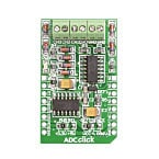
ADC Click by MikroElektronika (TMIK024)
Use Coupon Code: DVTLCL21
Last Chance Deals
ADC Click is an add-on board in the mikroBUS™ form factor (MIKROE-922). It includes a 12-bit Analog-to-Digital Converter (ADC) MCP3204 device that features 50k samples/second, 4 input channels, and low-power consumption (500nA typical standby, 2µA max). In addition, this board uses the industry-standard SPI communication interface. It is small in size and features convenient screw terminals for easier connections. By default, the board is set to use 3.3V of power. However, to use it with 5V systems, just place the PWR SEL SMD jumper in the 5V position.
Note: mikroBUS is an expansion board format used on several development boards from MikroElektronika, including TMIK013, TMIK016, TMIK017, TMIK021, TMIK022, and TMIK023.
MikroElektronika is a trusted third-party tool provider.
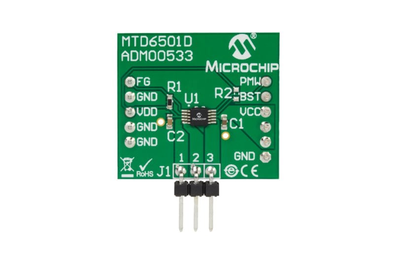
MTD6501D with Boost Mode Daughter Board (ADM00533)
Use Coupon Code: DVTLCL07
Last Chance Deals
dsPIC33EV256GM106 5V PIM for Motor Control Signal Board (MA330036)
Use Coupon Code: DVTLCL20
Last Chance Deals
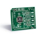
dsPIC33EP512GM710 Dual Motor Control Plug-In Module (MA330037)
Use Coupon Code: DVTLCL09
Last Chance Deals
The dsPIC33EP512GM710 motor control plug in module (PIM) comes with a 100-pin dsPIC33EP512GM710 TQFP device and enables users to explore the innovative features of the 70MIPS, 3.3V dsPIC33EPxxxGM family, including the ability to independently control dual motors. This PIM is specifically designed to be used with the Low Voltage Motor Control Bundle Development Bundle (DV330100), to control two BLDC motors by using both the internal (on-chip) and external op-amps (located on the development board). Supporting software is provided for this PIM to run Field Oriented Control (FOC) using AN1078 or AN1292.

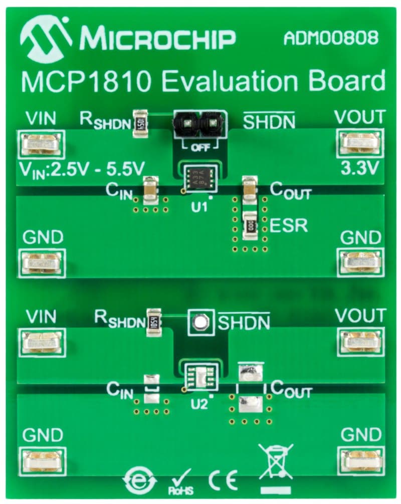
MCP1810 Evaluation Board (ADM00808)
Use Coupon Code: DVTLCL04
Last Chance Deals
The MCP1810 Evaluation Board features a typical circuit for the MCP1810 device, allowing the VIN voltage to be applied and the VOUT voltage measured. This allows the operational current to be measured, as well as a jumper to place the device into shutdown for the lowest current draw. A second, almost identical, unpopulated circuit is present to allow you to quickly prototype a circuit with your desired external component selection.
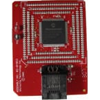
MPLAB ICD 64/80/100P TQFP HEADER (PIC18F97J60) (AC162064)
Use Coupon Code: DVTLCL25
Last Chance Deals
This is an optional header interface for the MPLAB ICD to free up the 2 debug pins when using the PIC18F97J60 family of devices. Please refer to the Development Tools Selector at www.microchip.com for up-to-date device support. Refer to DS51292.
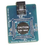
MPLAB ICD Header Interface for PIC18F87J10 (64/80P) (AC162062)
Use Coupon Code: DVTLCL24
Last Chance Deals
This is an optional header interface for the MPLAB ICD to free up the 2 debug pins when using the following devices: PIC18F87J10, PIC18F86J15, PIC18F86J10, PIC18F85J15, PIC18F85J10, PIC18F67J10, PIC18F66J15, PIC18F66J10, PIC18F65J15, or PIC18F65J10. Refer to DS51292.
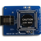
MPLAB ICD 64/80P HEADER PIC18F87J11 (AC162091)
Use Coupon Code: DVTLCL23
Last Chance Deals
This is an optional header interface for the MPLAB ICD to free up the 2 debug pins when using the PIC18F87J11 family of devices. Please refer to the Development Tool Selector for up-to-date support. Refer to DS51292.
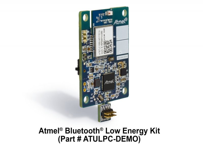
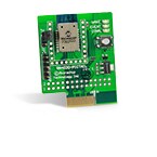
RN4020 Bluetooth Low Energy PICtail/PICtail Plus (RN-4020-PICTAIL)
Use Coupon Code: DVTLCL22
Last Chance Deals
The RN4020 PICtail/PICtail Plus is a development tool for prototyping new designs using the Microchip RN4020 module. The RN4020 PICtail has an onboard PIC18 to provide USB serial communications, allowing it to connect directly to a PC for simple demonstrations using RN4020 scripting capabilities. The RN4020 PICtail can also be plugged into a PIC Explorer 16 (DM240001) to develop feature rich applications using the PIC16, PIC18, and PIC32 family of microcontrollers.
Wi-Fi(R) Smart Device Enablement Kit (AC164165)
Use Coupon Code: DVTLCL02
Last Chance Deals
Microchip's Wi-Fi® Smart Device Enablement Kit is designed to accelerate adding Alexa Voice Control to your existing application, enabling rapid prototyping. The kit allows you to use an Alexa Smart Speaker or the Alexa App to control the board's GPIO, interrogate its sensors, and change its LED colors. By following our Alexa skill examples, you can create custom Alexa skills to further enhance the operation for your application.

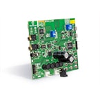
BM63 Bluetooth Audio Evaluation Board (BM-63-EVB)
Use Coupon Code: DVTLCL12
Last Chance Deals
The BM63 evaluation board is designed to provide users a platform on which to evaluate the BM63 Bluetooth 4.2 Dual Mode stereo audio module. The board has inputs for one MIC and one AUX jack, and a headset output jack. A CDA output connector is also available. Seven control buttons allow for easy audio control. The module can be configured to operate stand-alone or may be controlled by a host controller via a simple MCU connector. The kit includes a 15V adapter jack.
BM64 Bluetooth Audio Evaluation Board (BM-64-EVB-C1)
Use Coupon Code: DVTLCL16
Last Chance Deals
The BM-64-EVB-C1 enables the user to evaluate and demonstrate the functionality of the BM64 stereo audio module. The BM-64-EVB includes an integrated configuration and programming interface for plug-and-play capability, and also has status LEDs which enable rapid prototyping and faster time to market.
Along with the BM-64-EVB, software tools and applications are provided to demonstrate the Bluetooth connections to the on-board BM64 stereo audio module and to optionally configure or program it.

BM64 Bluetooth Audio Evaluation Board (BM-64-EVB-C2)
Use Coupon Code: DVTLCL15
Last Chance Deals
The BM64 evaluation board is designed to provide users a platform on which to evaluate the Class 2 BM64 Bluetooth 5.0 Dual Mode stereo audio module. The board has inputs for one MIC and one AUX jack, and a headset output jack. A CDA output connector is also available. Seven control buttons allow for easy audio control. The module can be configured to operate stand-alone or may be controlled by a host controller via a simple MCU connector. The kit includes a 15V adapter jack.

5.0 WVGA PCAP Display Board (AC320005)
Use Coupon Code: DVTLCL13
Last Chance Deals
The graphics 5.0" WVGA PCAP Display Board is designed for evaluating Microchip's graphics-display solution and graphics library for 32-bit microcontrollers. This daughter board is compatible with Multimedia Expansion Board II (DM320005-2). The board has a TFT 800x480 Display with 24-bit parallel RGB interface and with capacitive touch interface.
