We detect you are using an unsupported browser. For the best experience, please visit the site using Chrome, Firefox, Safari, or Edge. X
Maximize Your Experience: Reap the Personalized Advantages by Completing Your Profile to Its Fullest! Update Here
Stay in the loop with the latest from Microchip! Update your profile while you are at it. Update Here
Complete your profile to access more resources.Update Here!
0
$0.00
Item Qty
Your cart is empty.

We are continually expanding upon our PIC® microcontroller (MCU) portfolio, with an emphasis on reducing costs while developing products with a strong mix of peripherals including LCD controllers, Pulse-Width Modulators (PWMs), Analog-to-Digital Converters (ADCs), comparators, timers and communication. In addition to standard peripherals, we bring extra value to PIC MCUs by developing unique and exclusive peripherals that allow embedded lighting engineers to simplify their designs and create innovative applications and products. 

Peripheral Summary


Peripheral Capability Product Integration
High-Resolution PWM (HRPWM)  High-speed >17-bit PWM resolution All PIC® microcontrollers (MCUs) with NCO and CLC
Programmable Switch Mode Controller (PSMC)  Advanced, customizable high-speed 16-bit PWM module PIC16F178x family
Complementary Output Generation (COG)  Enhanced non-overlapping waveform generator PIC12F752, PIC16F753
Complementary Waveform Generation (CWG)  Non-overlapping waveform generator PIC10F32x family, PIC16F150x family
Numerically Controlled Oscillator (NCO)  Industry’s most precise, linear, low-cost 20-bit PWM PIC10F32x family, PIC16F150x family
Configurable Logic Cell (CLC)  Integrated combinational and sequential logic PIC10F32x family, PIC16F150x family

Peripheral Descriptions


High-Resolution PWM (HRPWM)


  • 17-bit PWM capability at high frequency
  • Utilizes integrated NCO and CLC
  • Higher-frequency operation
    • Reduced sizing of inductors and capacitors

Conventional PWM vs. HRPWM


  Conventional PWM HRPWM
PWM Resolution 16-bit Variable
PWM Clock Frequency 16 MHz 16 MHz
Target Switching Frequency 500 kHz 500 kHz
Target Period Width 1 ÷ 500 kHz = 2 µs 1 ÷ 50 0kHz = 2 µs
Best PWM Pulse Adjustment 1 ÷ 16 MHz = 62.5 ns 15.26 ps*
Maximum Number of Steps per Period 2 µs ÷ 62.5 ns = 32 2µs ÷ 15.26 ps = 131,072
Effective Full-Range PWM Resolution log232 = 5 bits log2131,072 = 17 bits

* Refer to Application Note

Programmable Switch Mode Controller (PSMC)


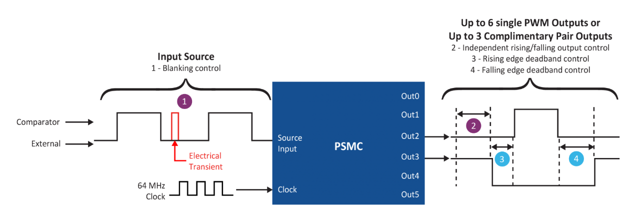
  • Single 16-bit PWM with up to six steerable outputs
  • Complementary 16-bit PWM with up to three steerable output pairs
  • Clock sources: External, system clock, independent 64 MHz oscillator
  • Input sources: Comparators, external pins
  • Blanking control for transient filtering
  • Independent rising/falling edge control
  • Dead band with independent rise and fall control
  • Polarity control/auto shutdown and restart
  • Flexible PWM output modes
  • Burst Mode: Externally control activate/deactivate

Complementary Waveform Generator (CWG) Complementary Output Generator (COG)


  • Provides non-overlapping complementary waveform
  • Various input sources inclusive of: Comparators, PWM, CLC, NCO
  • Blanking control for transient filtering (COG only)
  • Phase control for output delay (COG only)
  • Independent rise and fall
  • Dead band control
  • Auto shutdown/restart
  • Polarity control

Numerically Controlled Oscillator (NCO)
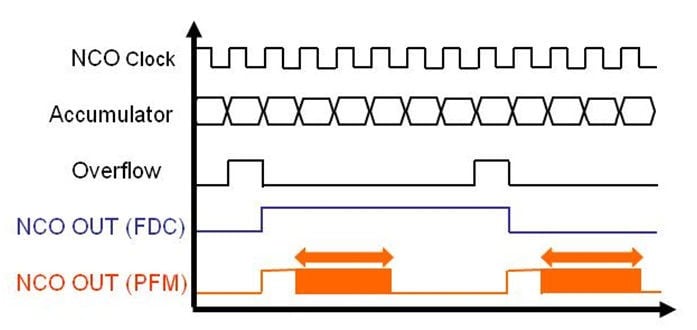

  • 20-bit PWM frequency resolution with linear control
  • Independent 16 MHz clock input
  • 16-bit numeric frequency control
    • 500 kHz max output, 15 Hz per step
  • Two output modes
    • Fixed 50% Duty Cycle (FDC)
    • Pulse Frequency Modulation (PFM)

Configurable Logic Cell (CLC)


  • User-configurable real-time logic control
    • CLC configuration GUI for quick-turn development
  • Combinational logic functions
    • AND/OR/XOR/NOT/NAND/NOR/XNOR
  • State functions/clock
    • D flip-flop, JK flip-flop, D latch, SR latch
  • Input sources
    • Pins
    • Peripherals
  • Output available to:
    • External pins
    • Other peripherals
  • Operation while in sleep
  • Configurable via custom GUI

Lighting Products


Documents


Application Notes


Title
Combining the CLC and NCO to Implement a High Resolution PWM Download
Bit Banged LIN Slave Node for PIC16 & PIC18 Download
High-Efficiency Solutions for Portable LED Lighting Download
Dimming AC Incandescent Lamps Using A PIC10F200 Download
Alternate Use of the HV9922 as an Off-line, Non-isolated, 50 to 100 mA Auxiliary Power Supply Download
HV9910B: Constant, Off-time, Buck-based LED Driver Download
Buck Configuration High-Power LED Driver Download
Improving the Efficiency of a HV9930/AT9933 Boost-Buck Converter Download
A Technique to Increase the Frequency Resolution of PICmicro MCU PWM Modules Download
Dimming Power LEDs Using a SEPIC Converter and MCP1631 PIC Attach PWM Controller Download
Compatibility and Functional Differences between the HV9961 and HV9910B LED Drivers Download
Offline Power Converter for High-Brightness LEDs Using the PIC16HV785 Microcontroller Download
Designing with HV Microcontrollers Download
HV9910B: Buck-based LED Driver Download
Designing a Boost-Switching Regulator with the MCP1650 Download
Transformerless Power Supplies: Resistive and Capacitive Download
Isolated Constant Power Converter Using the HV9922 Download
DALI Control Gear Download
A Digital Constant Current Power LED Driver Download
Digitally Addressable Lighting Interface (DALI) Communication Download
AT9933: Designing a Boost-Buck converter with the HV9930 Download
Software PWM Generation for LED Dimming and RGB Color Applications Download
Maximum Power Solar Converter Download

Firmware


The software in this section is subject to the U.S. Export Administration Regulations and other U.S. law, and may not be exported or re-exported to certain countries or to persons or entities prohibited from receiving U.S. exports (including Denied Parties, entities on the Bureau of Export Administration Entity List, and Specially Designated Nationals).

DALI Code Library


Beta code library available now

Digital Addressable Lighting Interface (DALI) is a standard lighting control protocol for large networked lighting systems. DALI provides bi-directional communications with uniquely addressed light sources. This allows for customized lighting schemes and the ability for the light source to relay information back to the controller (ie. light output level, color, energy usage, etc.).

  • 'C' based firmware library
  • Control Device (master) and Control Gear (slave) libraries
  • Automated commissioning
  • Firmware implementation on any 8-bit PIC® microcontroller
    • PIC microcontroller requirements
      • One 8-bit timer, one 16-bit timer
      • EEPROM or Emulated EEPROM (self-write Flash)
      • ~4KW Flash program memory footprint (final code size TBD)
    • Compliance
      • IEC 62386-101 (DALI general system requirements)
      • IEC 62386-102 (DALI general system requirements – control gear)
      • Future support for IEC 62386-2xx implementation (particular requirements for control gear; e.g. LED, fluorescent, etc.)
 
Downloads

Reference Designs


Title Description Availability Part#
MCP1630 Boost Mode LED Driver Demo Board Uses MCP1630V and a PIC12F device to drive up to 30W LED output power. Input voltage can be 9 - 16V. A string of 5 Cree 1W LEDs is provided with the kit. Now MCP1630DM-LED2
HV9861A LED Driver Demoboard Boost Assisted, Valley Fill, 120VAC Input, 7W Output, 350mA, 20V, Power Factor ~ 93% demo board Now HV9861ADB2
HV9910B LED Driver Demoboard Off-Line, High Brightness, LED Driver Demo Board Now HV9910BDB7
HV9961 LED Driver Demoboard 21-Watt Universal AC LED Driver Demoboard with Accurate Average-Mode Constant Current Control Now HV9961DB1
HV9922 LED Driver Demoboard Universal Off-line LED Driver Demoboard Now HV9922DB1
HV9930 LED Driver Demoboard High Brightness LED Driver IC Demoboard Now HV9930DB1
MCP19114 Flyback Standalone Evaluation Board MCP19114-Flyback Standalone Evaluation Board and Graphical User Interface (GUI) demonstrate the MCP19114 performance in a synchronous Flyback topology. Now ADM00578
MCP19117 Flyback Evaluation Board MCP19117-Flyback Standalone Evaluation Board and Graphical User Interface (GUI) demonstrate the MCP19117 performance in a synchronous Flyback topology. Now ADM00663