We detect you are using an unsupported browser. For the best experience, please visit the site using Chrome, Firefox, Safari, or Edge. X
Maximize Your Experience: Reap the Personalized Advantages by Completing Your Profile to Its Fullest! Update Here
Stay in the loop with the latest from Microchip! Update your profile while you are at it. Update Here
Complete your profile to access more resources.Update Here!
Item Qty
Your cart is empty.

LED Lighting

At the forefront of the most efficient incandescent alternatives are LED and fluorescent technologies. Both have advantages and technical challenges and provide significantly improved efficacy (lumens/watt) over incandescent lighting. Additionally both technologies provide opportunities to add intelligence beyond simple incandescent light bulb replacement.

Advantages

  • Best overall efficiency
    • ~75% less energy than incandescent
    • ~25% input energy = light
    • More than 100 lumens/watt (efficacy)
  • Long life: >50,000 hours
  • No warm-up
  • No radiated heat
  • Good in indoor and outdoor applications

Disadvantages

  • Near-term expense
  • Requires electronic drive
  • Requires thermal solution to remove conducted heat

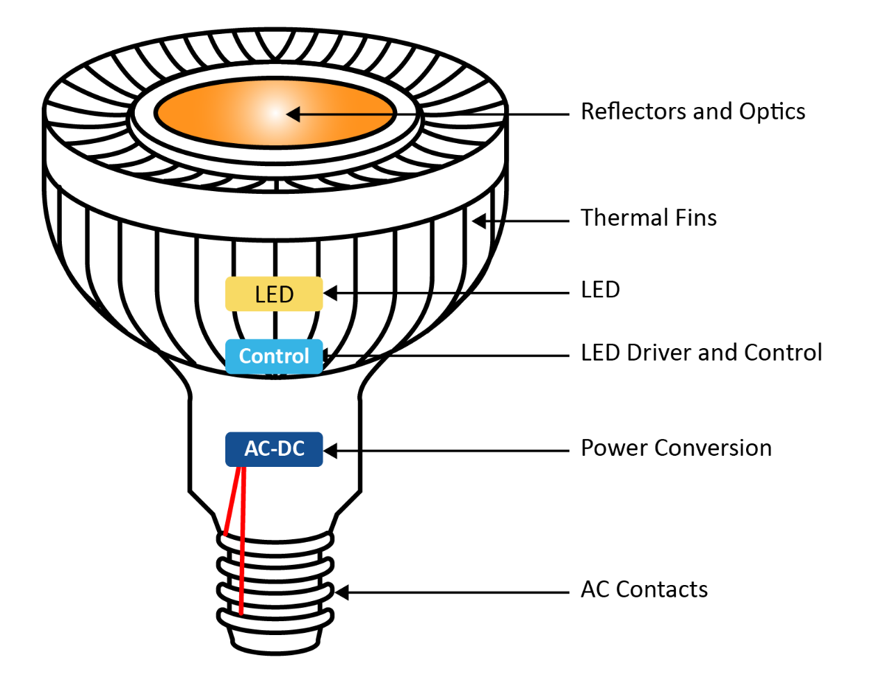
Unlike an incandescent or fluorescent light source, an LED does not radiate heat. Rather, the heat is conducted via the back side of the LED semiconductor material. This creates a technical obstacle as excessive heat can deteriorate LED performance, function and overall lifetime. To properly remove the heat in a high-power LED application, you may need to utilize a thermal heat sink or active fan or actively reduce lumen output based on temperature.

Controlling an LED


LED light output is a direct function of the current flow. Too little current and the light will dim; too much current and lifetimes will be shortened. A typical LED driver is a DC power supply that provides converted AC or DC power to directly control the LED via constant current, Pulse Width Modulation (PWM) or other variations. The LED driver must also provide high efficiencies and Power Factor Correction (PFC) while protecting the light from AC line voltage fluctuations.

Constant Current Method


  • Light output maintained by constant current level
  • Dimming control via varying current level
  • Requires high-resolution current control

Modulated Current Method


  • Fixed current drive chopped by PWM
  • Dimming control via varying PWM duty cycle

LED drivers can be designed to offer dimming and RGBW color mixing capabilities by either providing a high-resolution PWM (or variants such as Variable Frequency Modulation) signal or varying the constant current.

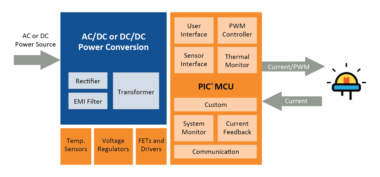
Efficient Power Conversion


Our solutions can support any LED drive methodology and add additional capabilities beyond that of traditional lighting solutions. The flexibility of these solutions allows for simplified attachment to existing designs or the development of full Switch Mode Power Supply (SMPS)-based intelligent solutions.

SMPS with PIC® Microcontroller and Analog Products


  • Increased MCU integration
  • Fully customizable
  • Increased efficiency
  • Power Factor Correction (PFC)
  • Flexible topologies
  • Simplified modifications via firmware updates
  • Closed-loop control feedback
  • High-performance PWM and current control variation
  • Intelligent control capabilities

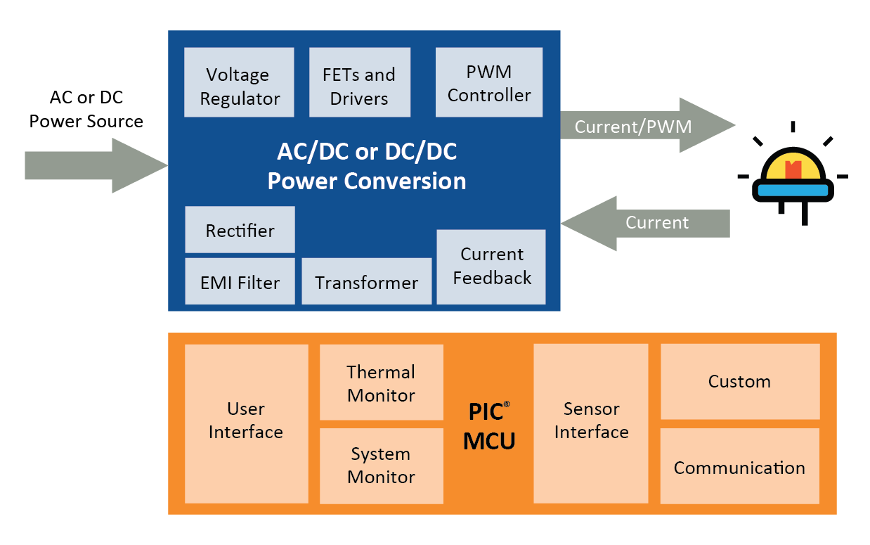
PIC Microcontroller Attach to Basic Power Supply

  • Simplified design-in
  • Customizable features
  • Simplified modifications via firmware updates
  • Intelligent control capabilities

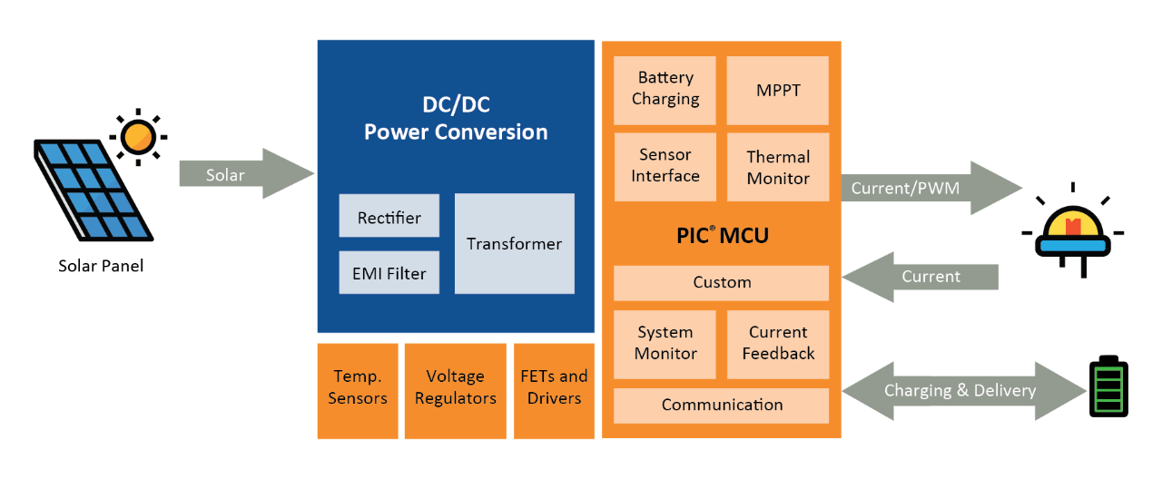
Energy Harvesting and Battery Charging

  • PIC MCU-controlled power conversion and battery storage
  • Peak power tracking control, charging and power delivery
  • Customizable MPPT and battery charging algorithms
  • Support for various power supply topologies
  • Intelligent control capabilities

The input supply voltage and the LED forward voltage characteristics determine the SMPS topology that is required. The SMPS topologies utilized to regulate the power within LED lighting applications are the same as those used within a power supply application. Each SMPS topology has its advantages and determining the proper topology is dependent upon the specific application requirements. Refer to the table below for topology guidelines.

Common Power Conversion Topologies


General SMPS Guidelines


Topology Vin vs. Vout Relationship Power Range (max) Peak Efficiency
Buck Vin > Vout 1000W >90%
Boost Vin < Vout 150W >90%
Buck/Boost Vout < Vin < Vout 150W >80%
SEPIC, Cuk, Zeta Vout < Vin < Vout 150W >90%
Flyback Vout < Vin < Vout 150W >80%
Resonant Vout < Vin < Vout 500W >90%
Push-Pull Vout < Vin < Vout 1KW >90%

Intelligent Control Capabilities


In addition to efficient power conversion and LED control, our lighting solution provides opportunities to further enhance your lighting application through product differentiation and increased user experience.

  • Custom user interface and control
  • Communication and networking
  • Environmental sensing
    • Motion, external light source, etc.
  • Daylight harvesting and auto-dimming
  • Thermal management
    • Active and passive
  • Smooth dimming control
  • Color mixing
  • Closed-loop lighting control
  • Color and lumen compensation
  • System health monitoring
  • Predictive failure monitoring
  • Remote fault detection
  • Energy monitoring and control
  • Energy harvesting
  • Solar, radio, etc.
  • Battery management and charging
  • Fully customizable options

Lighting Products


Documents


Application Notes


Title
Combining the CLC and NCO to Implement a High Resolution PWM Download
Bit Banged LIN Slave Node for PIC16 & PIC18 Download
High-Efficiency Solutions for Portable LED Lighting Download
Dimming AC Incandescent Lamps Using A PIC10F200 Download
Alternate Use of the HV9922 as an Off-line, Non-isolated, 50 to 100 mA Auxiliary Power Supply Download
HV9910B: Constant, Off-time, Buck-based LED Driver Download
Buck Configuration High-Power LED Driver Download
Improving the Efficiency of a HV9930/AT9933 Boost-Buck Converter Download
A Technique to Increase the Frequency Resolution of PICmicro MCU PWM Modules Download
Dimming Power LEDs Using a SEPIC Converter and MCP1631 PIC Attach PWM Controller Download
Compatibility and Functional Differences between the HV9961 and HV9910B LED Drivers Download
Offline Power Converter for High-Brightness LEDs Using the PIC16HV785 Microcontroller Download
Designing with HV Microcontrollers Download
HV9910B: Buck-based LED Driver Download
Designing a Boost-Switching Regulator with the MCP1650 Download
Transformerless Power Supplies: Resistive and Capacitive Download
Isolated Constant Power Converter Using the HV9922 Download
DALI Control Gear Download
A Digital Constant Current Power LED Driver Download
Digitally Addressable Lighting Interface (DALI) Communication Download
AT9933: Designing a Boost-Buck converter with the HV9930 Download
Software PWM Generation for LED Dimming and RGB Color Applications Download
Maximum Power Solar Converter Download

Firmware


The software in this section is subject to the U.S. Export Administration Regulations and other U.S. law, and may not be exported or re-exported to certain countries or to persons or entities prohibited from receiving U.S. exports (including Denied Parties, entities on the Bureau of Export Administration Entity List, and Specially Designated Nationals).

DALI Code Library


Beta code library available now

Digital Addressable Lighting Interface (DALI) is a standard lighting control protocol for large networked lighting systems. DALI provides bi-directional communications with uniquely addressed light sources. This allows for customized lighting schemes and the ability for the light source to relay information back to the controller (ie. light output level, color, energy usage, etc.).

  • 'C' based firmware library
  • Control Device (master) and Control Gear (slave) libraries
  • Automated commissioning
  • Firmware implementation on any 8-bit PIC® microcontroller
  • PIC microcontroller requirements
  • One 8-bit timer, one 16-bit timer
  • EEPROM or Emulated EEPROM (self-write Flash)
  • ~4KW Flash program memory footprint (final code size TBD)
  • Compliance
  • IEC 62386-101 (DALI general system requirements)
  • IEC 62386-102 (DALI general system requirements – control gear)
  • Future support for IEC 62386-2xx implementation (particular requirements for control gear; e.g. LED, fluorescent, etc.)

Downloads

Reference Designs


Title Description Availability Part#
MCP1630 Boost Mode LED Driver Demo Board Uses MCP1630V and a PIC12F device to drive up to 30W LED output power. Input voltage can be 9 - 16V. A string of 5 Cree 1W LEDs is provided with the kit. Now MCP1630DM-LED2
HV9861A LED Driver Demoboard Boost Assisted, Valley Fill, 120VAC Input, 7W Output, 350mA, 20V, Power Factor ~ 93% demo board Now HV9861ADB2
HV9910B LED Driver Demoboard Off-Line, High Brightness, LED Driver Demo Board Now HV9910BDB7
HV9961 LED Driver Demoboard 21-Watt Universal AC LED Driver Demoboard with Accurate Average-Mode Constant Current Control Now HV9961DB1
HV9922 LED Driver Demoboard Universal Off-line LED Driver Demoboard Now HV9922DB1
HV9930 LED Driver Demoboard High Brightness LED Driver IC Demoboard Now HV9930DB1
MCP19114 Flyback Standalone Evaluation Board MCP19114-Flyback Standalone Evaluation Board and Graphical User Interface (GUI) demonstrate the MCP19114 performance in a synchronous Flyback topology. Now ADM00578
MCP19117 Flyback Evaluation Board MCP19117-Flyback Standalone Evaluation Board and Graphical User Interface (GUI) demonstrate the MCP19117 performance in a synchronous Flyback topology. Now ADM00663