High-Volume Data Transfer With EMI Solutions
Offering a variety of key features for complex and challenging computing applications, many of our Embedded Controllers (ECs) contain a unique interface to transfer large amounts of data between the EC and the host processor. Similar devices normally provide an Advanced Configuration and Power Interface (ACPI) that can transfer only 1 byte at a time or a mailbox that can transfer 16 bytes at a time between the EC and the host processor. The Embedded Memory Interface (EMI) found on our ECs allows the transfer of multiple blocks of data up to 32 KB at a time. This allows you to perform functions, such as remote BIOS updates, much faster than with other devices currently available in the market.
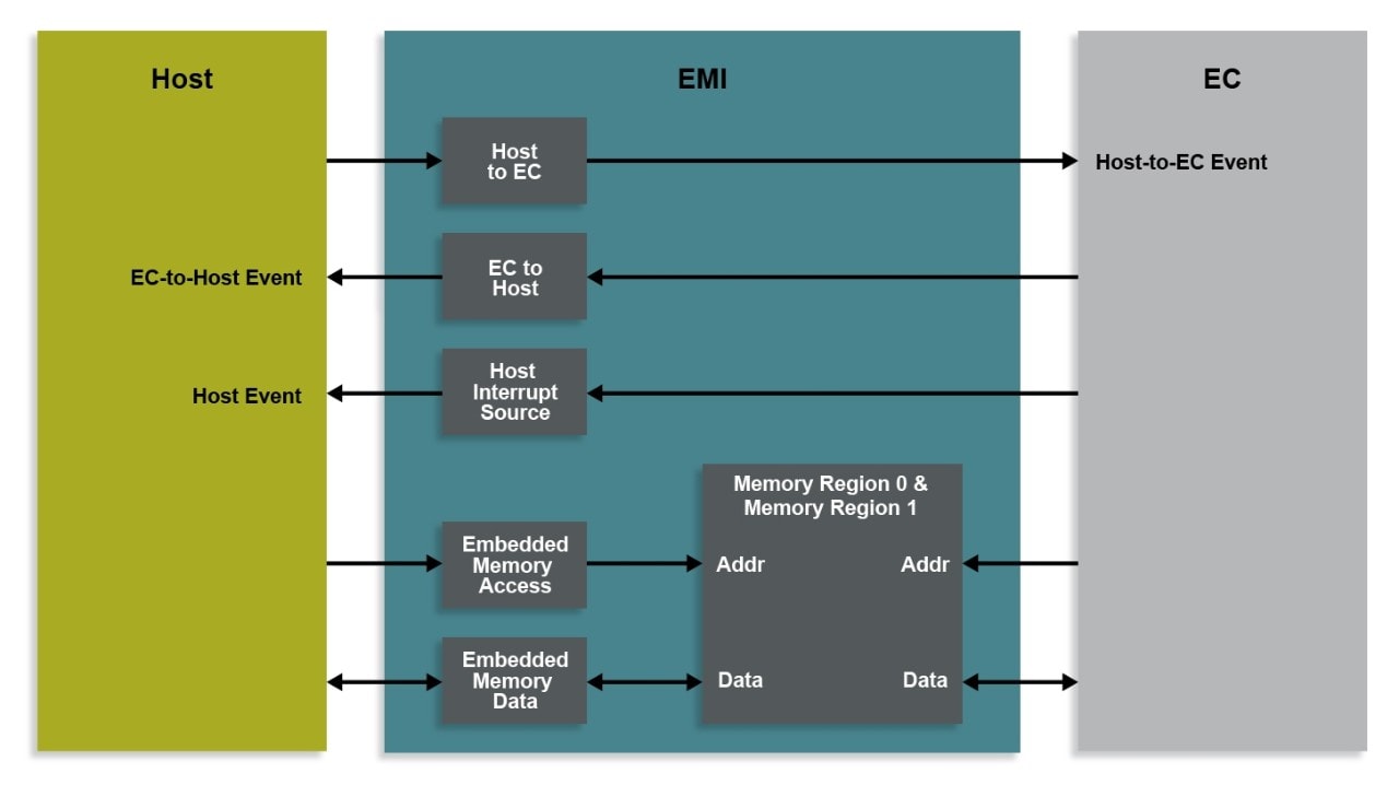
The EMI provides a standard run-time mechanism for the system host to communicate with the EC and other logic devices. It includes 13 byte-addressable registers in the host’s address space, as well as 22 bytes of registers that are accessible only by the EC. The EMI can be used by the host to access bytes of memory designated by the EC without requiring any assistance from the EC. The EC may configure these regions of memory as read-only, write-only or read/write capable.

The EMI is composed of a mailbox, a direct memory interface and an Application ID register. The mailbox contains two registers, the HOST-to-EC Mailbox Register and the EC-to-HOST Mailbox Register, that act as a communication portal between the system host and EC. When the HOST-to-EC Mailbox Register is written, an interrupt is generated to the EC. Similarly, when the EC-to-HOST Mailbox Register is written, an interrupt is generated to the system host. The source of the system host interrupt may be read in the Interrupt Source Register. These interrupt events may be individually prevented from generating a Host Event via the Interrupt Mask Register.
The direct memory interface, which is composed of a byte-addressable 16-bit EC Address Register and a 32-bit EC Data Register, permits the host to read or write a portion of the EC’s internal address space. The EC may enable up to two regions of its internal address space to be exposed to the system host. The system host may access these memory locations without intervention or assistance from the EC.
The EMI can be configured so that data transfers between the EMI data bytes and the 32-bit internal address space may be multiple bytes, while host I/O is always executed a byte at a time.
When the host reads one of the four bytes in the EMI’s data register, data from the internal 32-bit address space, at the address defined by the EMI’s address register, is returned to the host. This read access will load 1, 2 or 4 bytes into the data register depending on the configuration of the ACCESS_TYPE bits. Similarly, writing one of the four bytes in the data register will write the corresponding byte(s) from the data register into the internal 32-bit address space as indicated by the ACCESS_TYPE bits. This configuration option ensures that data the EC treats as 16-bit or 32-bit will be consistent in the host, even though one byte of the data may change between two or more 8-bit accesses by the host.
In addition, there is an auto-increment function for the EMI’s address register. When enabled, the host can read or write blocks of memory in the 32-bit internal address space by repeatedly accessing the EMI’s data register without requiring host updates to the EMI’s address register.
Finally, the Application ID Register may be used by the host to provide an arbitration mechanism if more than one software thread requires access through the EMI interface.
Embedded Memory Map
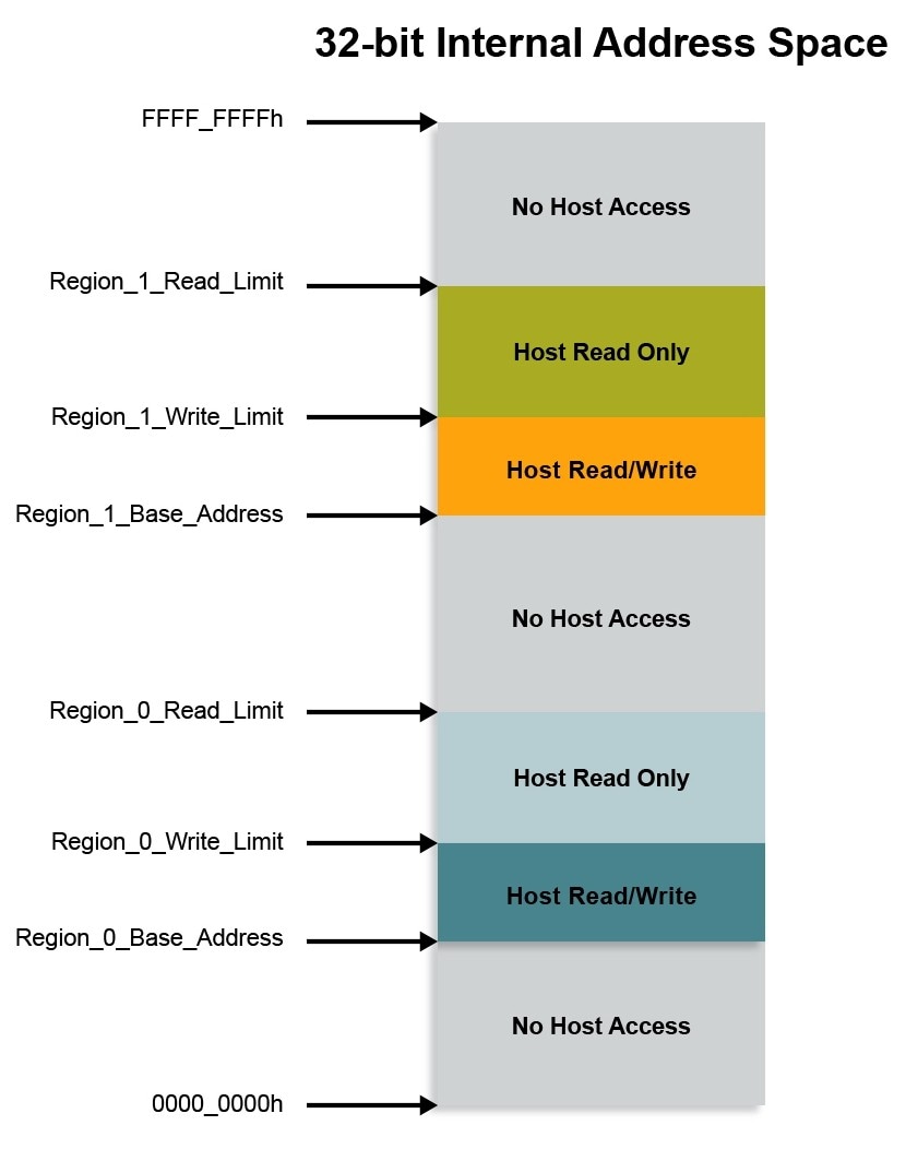
Each EMI provides direct access for the host into two windows in the EC’s 32-bit internal address space.
The Base addresses, the Read limits and the Write limits are defined by registers that are in the EC’s address space and cannot be accessed by the host. In each region, the Read limit need not be greater than the Write limit. The regions can be contiguous or overlapping. For example, if the Region 0 Read limit is set to 0 and the Write limit is set to a positive number, then the EMI defines a region in the EC memory that the EC can read and write but is write-only for the host. This might be useful for storage of security data that the host might send to the EC, which should not be readable in the event that a virus invades the host.
Each window into the EC memory can be as large as 32 KB in the 32-bit internal address space.
If you would like to discover how to take advantage of the power of the EMI for your computing system, please download the MEC170x data sheet.
