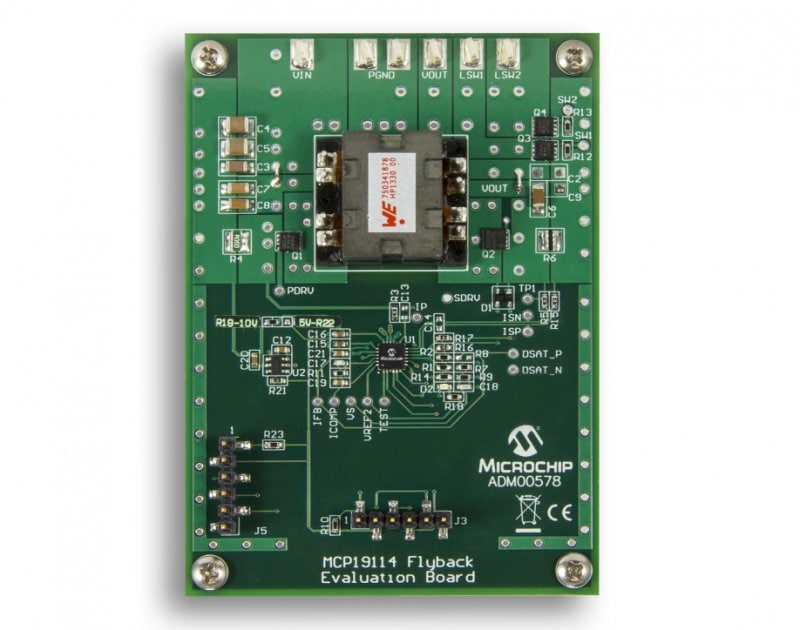
Part Number: ADM00578
MCP19114 FLYBACK STANDALONE EVALUATION BOARD
• Ceramic and bulk capacitors on the input reduce RMS ripple current and tame input voltage deviation caused by load transients
• Ceramic capacitors on the output reduce voltage ripple and provide energy to the output while the primary side is being re-energized
• PC software provides simple interface to evaluating the evaluation board
• Vin range: 8V to 14V
• Adjustable Vout range: 0V to 50V
• Maximum output current: 500mA with proper air flow
• Programming and I2C communication headers
• The factory programmed source code is available
Overview
The MCP19114-Flyback Standalone Evaluation Board and Graphical User Interface (GUI) demonstrate the MCP19114 performance in a synchronous Flyback topology. It is configured to regulate load current, and is well suited to drive LED loads. Nearly all operational and control system parameters are programmable through the integrated PIC MCU core. The MCP19114 evaluation board comes preprogrammed with firmware designed to operate with the GUI interface. Microchip’s MPLABX IDE (Integrated Development Environment) can be used to develop and program user-defined firmware, thus customizing it to the specific application. The evaluation board contains headers for ICSPTM (In-Circuit Serial Programming) as well as I2C™ communication. Several test points have been designed into the PWB for easy access and development purposes. The MCP19114-Flyback Standalone Evaluation Board also demonstrates an optimized PCB (Printed Circuit Board) layout that minimizes parasitic inductance, while increasing efficiency and power density. Proper PCB layout is critical to achieve optimum MCP19114 operation as well as power train efficiency and noise minimization.
Documentation
|
Title
|
|||
|---|---|---|---|
| Analog and Interface Product Selector Guide | Download | ||
| MCP19114 Flyback Standalone Evaluation Board (ADM00578) Gerbers | Download | ||
| MCP19114 Flyback Standalone Evaluation Board (ADM00578) Schematics | Download | ||
| MCP19114 Flyback Standalone Evaluation Board (ADM00578) BOM | Download | ||
| MCP19114/MCP19115 User's Guide | Download | ||
| MCP19114/MCP19115 Programming Specification | Download | ||
| MCP19114/MCP19115 Data Sheet | Download |
Software
|
Title
|
Date
|
||
|---|---|---|---|
| MCP19114_5 Design Analyzer v1.0 | Download | 21 Mar 2014 |