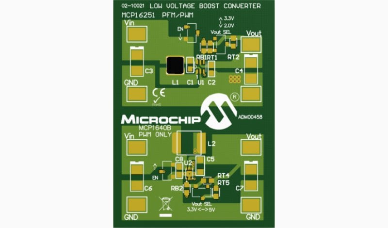
Part Number: ADM00458
MCP16251 AND MCP1640B SYNCHRONOUS BOOST CONVERTERS EVALUATION BOARD
Output, 3V Input
Overview
The MCP16251 and MCP1640B Synchronous Boost Converters Evaluation Board is used to evaluate and demonstrate Microchip Technology’s MCP16251 and MCP1640B products. This board demonstrates the MCP16251/MCP1640B in two boost-converter applications with multiple output voltages. It can be used to evaluate both package options (SOT-23-6 and 2x3 mm 8-(T)DFN). The MCP16251 and MCP1640B Synchronous Boost Converters Evaluation Board was developed to help engineers reduce the product design cycle time. Three common output voltages can be selected: 2.0V, 3.3V and 5.0V. The output voltage can be changed with a mini-dip switch that changes the external resistor divider. A switch connected to the EN pin is used to enable and disable the converters. When enabled, the MCP16251/MCP1640B will regulate the output voltage; when disabled, the MCP16251/MCP1640B disconnects the path from input to output for “true-disconnect”.
Devices Supported: MCP16251, MCP1640B
Documentation
|
Title
|
|||
|---|---|---|---|
| MCP16251/MCP16252 Data Sheet | Download | ||
| MCP1640/B/C/D Data Sheet | Download | ||
| MCP16251 and MCP1640B Synchronous Boost Converters Evaluation Board User's Guide | Download | ||
| MCP16251 and MCP1640B Sync Boost Converters Eval Board (ADM00458) Schematic | Download | ||
| MCP16251 and MCP1640B Sync Boost Converters Eval Board (ADM00458) BOM | Download | ||
| MCP16251 and MCP1640B Sync Boost Converters Eval Board (ADM00458) Gerbers | Download |