

Part Number: PIC16F1947 Lighting Control Console
PIC16F1947 LIGHTING CONTROL CONSOLE
Design Highlights:
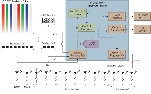
PIC16F1947 Lighting Control Interface
- DALI and DMX512 communications
- 8 sliders for multiple channel color mixing
- 11 buttons for customizable user control
- 14 LED status indicators
Isolated DALI Interface
- 2-wire header & RJ45 connectors
- Current limited DALI power supply
- DALI ‘C’ Library Stack
- Resides within PIC16F1947
Isolated DMX512A Interface
- XLR5 and RJ45 connectors
- Isolated transceiver
- DMX512A ‘C’ Library Stack
- Resides within PIC16F1947
Additional Resources
Theory of Operation
The lighting control console is an application example utilizing the Lighting Communications Development Platform. The application firmware is based upon custom control firmware paired with Microchip’s DALI & DMX512 Code Libraries and provides the capability of controlling multiple main boards via DALI and/or DMX512. User interface is provided via the multiple sliders and buttons with feedback via the LED display, indicator LEDs, and visible control of RGBW LED on main board.
PIC16F1947 Lighting Control Console
The lighting console with DMX512A firmware has 3 modes of operation:
- Button ‘A’: Manual output control and scene programming
- Button ‘B’: Automatic scenes (Demonstration Mode)
- Button ‘C’: Semi-automated scene playback
Manual Output Mode:
Pressing button ‘A’ (S10) of the 3 mode buttons will select this mode: button ‘A’ indicator illuminated with LED display ‘PrG’.
Adjusting the sliders automatically updates the appropriate DMX512 channels and transmits immediately. Sliders 1-8 are assigned address 1-8 from left to right (ie. Slider 1 = address ‘1’ (RED) and is addressing LED address ‘1’ of the main board, Slider 6 = address ‘6’ (GREEN) is addressing LED address ‘6’ of main board).
A specific scene can be saved by pressing one of the 8 buttons under the sliders. That scene will then be associated with that specific button – up to 8 unique scenes can be assigned to buttons S2-S9.
Automatic Scene Mode:
Pressing button ‘B’ (S11) of the 3 mode buttons will select this mode: button ‘B’ indicator illuminated with LED display ‘Aut’
The console will begin transmitting and rotating through the scenes associated to each button programmed in the prior mode. Slider 7 sets the fade time and slider 8 sets the transition speed between changes. The scenes will automatically change at the speed and delay set by these sliders. (Slider speed control: bottom = fastest / top = slowest).
Semi-Automated Scene Mode:
Pressing button ‘C’ (S12) of the 3 mode buttons will select this mode: button ‘C’ indicator illuminated with LED display ‘SEL’.
In this mode the scene can be selected by pressing the buttons under the sliders. The slider above the specific button will determine the speed at which the scene will transition (Slider speed control: bottom = fastest / top = slowest).
Contact your local sales representative to see a working demonstration of the Lighting Control Console.
For comments or suggestions on Microchip's Lighting Solutions - please Schedule a Call with Our Team
For comments or suggestions on Microchip's Lighting Solutions - please email us at lighting@microchip.co