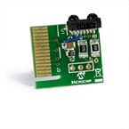
Part Number: AC164124
IRDA PICTAIL PLUS DAUGHTER BOARD
- Infrared optical sensor.
- PICtail™ Plus Daughter Board connection interface
Signal Interface
| Functions | I/O | Pin | Description |
| RX | I | U1RX/U2RX | UART Receive |
| TX | O | U1TX/U2TX | UART Transmit |
Overview
The IrDA PICtail™ Plus Daughter Board is designed to operate in conjunction with Microchip’s Explorer 16 or other development boards with a PICtail Plus connector and AN1071 IrDA Standard Stack for Microchip 16-bit and PIC32 devices to create an IrDA-enabled development and evaluation platform. The IrDA Stack is written to operate with the IrDA-enabled UARTs on the 16-bit PIC24 MCUs, PIC32 MCUs and dsPIC33 DSCs.
Additional Resources
Getting Started
To get started, an Explorer 16 development board is required. All Explorer 16 development boards are shipped with connector J5 installed. The IrDA® Standard PICtail Plus Daughter Board should be inserted into one of the top two sockets of J5. The orientation of the IrDA Standard PICtail Plus Daughter Board should be such that the optical sensors points toward the prototyping area on the Explorer 16 development board. If the board is inserted into the top most socket, UART1 must be utilized for infrared communication. If the board is inserted into the second top most sockets, UART2 must be utilized for infrared communication.
The IrDA™ Standard PICtail Plus Daughter Board can be used in conjunction with the IrDA Standard Stacks for Microchip 16-bit and PIC32 microcontrollers (see application note AN1071). The demonstration projects provided with the stack can be programmed into an Explorer 16 demonstration board and interact with either Explorer 16 demonstration board, or another device that also supports the pertinent IrDA® Standard protocol.