Smarter Stepper Motors with AVR® EB MCUs
Learn how to start micro-stepping stepper motors with our reference design on the AVR® EB family of MCUs.
Introducing AVR® EB MCU for Smart Motor Control
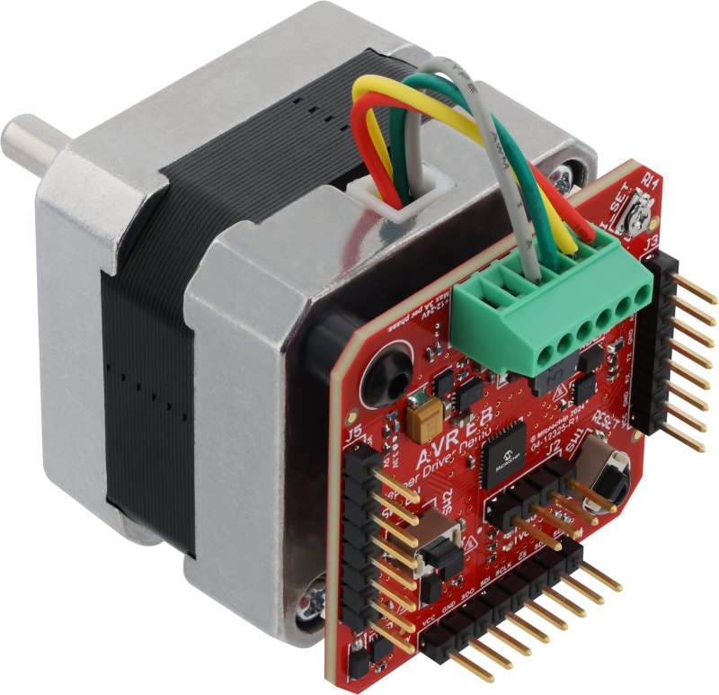
The AVR® EB family of microcontrollers (MCUs) are designed for motor control with the new Timer/Counter Type-E (TCE) and Waveform Extension (WEX) peripherals to generate control signals for motors. Our new reference design on AVR EB, based on the Multi-Phase Power Board (MPPB), uses these peripherals to create a Smart Stepper Motor Driver that mounts on the back of a NEMA 17 sized stepper motor (42 mm × 42 mm).
 |
The Smart Stepper Motor gets its intelligence from the ability of the microcontroller to directly adjust the control signals from sensors and/or telemetry. This creates a more independent solution that can off-load tasks from the primary controller in the system. For instance, if the stepper drove a dial indicator, there might be rotary encoders or microswitches to provide positional feedback to determine if the dial is in the correct position.
The AVR16EB32 microcontroller at the heart of this example implements micro-stepping up-to 1/32 for smooth, quiet motor control. Half steps and full steps are also possible in the example. There are two versions of firmware available for this design. One version uses the motor to move a precise number of steps at a given speed. This yields the best performance possible. The other version of the firmware mimics the standard DIR/STEP interface commonly seen on ASICs. This version is the fastest to implement into an existing system.
Theory of Operation
The reference design supports power inputs between 12V and 30V, with up-to 3A per phase. Motor current control is achieved in two ways—by software and by peripheral. The firmware on the microcontroller performs calculations to determine the required on-time to match the expected current waveform. Additionally, the microcontroller can also use two of its on-board Analog Comparators (AC) peripherals in conjunction with the Configurable Custom Logic (CCL) and Event System (EVSYS) peripherals to shut down the waveform if the current through the H-bridge reaches a programmed level.
The control signals from the microcontroller are connected to MIC4605-1 Gate Drivers, which each control a half-bridge. On the low-side of each H-bridge is a 0.01 Ω (10 mΩ) current shunt connected to MCP6C26-100 Zero-Drift, Current Sense Amplifier. This amplifier provides a fixed gain of 100x for a response of 1 V/A.
The microcontroller I/O has been pre-allocated to specific functionalities—such as analog signals, SPI, I2C and/or UART. Since most of these functions do not require special circuitry, they can be reassigned or changed in software as needed.
Conclusion
The hardware peripherals on AVR EB are invaluable for creating the signals required to control stepper motors. By directly generating the signals in the microcontroller, advanced functionalities can be implemented for a more independent system design. For more information about the design, such as the PCB files, schematics and test data, please visit the reference design page. More information about the AVR EB family is available here.
