Overview of LX4580 Power Supplies and Supply Fault Management
Learn more about the LX4580 analog front-end Integrated Circuit (IC) for actuation systems and its multiple supply rails and regulators as well as regulator fault management.
Managing Supply Rails and Faults using LX4580
This is the fourth of a series discussing topics around LX4580 implementations. The LX4580 is an analog front end for high-reliability motor-actuator control systems working under stringent standards such as DO-160 for avionics in airborne systems. The LX4580 interfaces with dual microcontrollers (MCUs) or Field-Programmable Gate Arrays (FPGAs) in redundant COM/MON system architectures, and features ECC encoding to provide 1 bit error correction and 2-bit error detection. Sequential logic is implemented with Triple Mode Redundancy (TMR) to protect against Single-Event Upsets (SEUs).
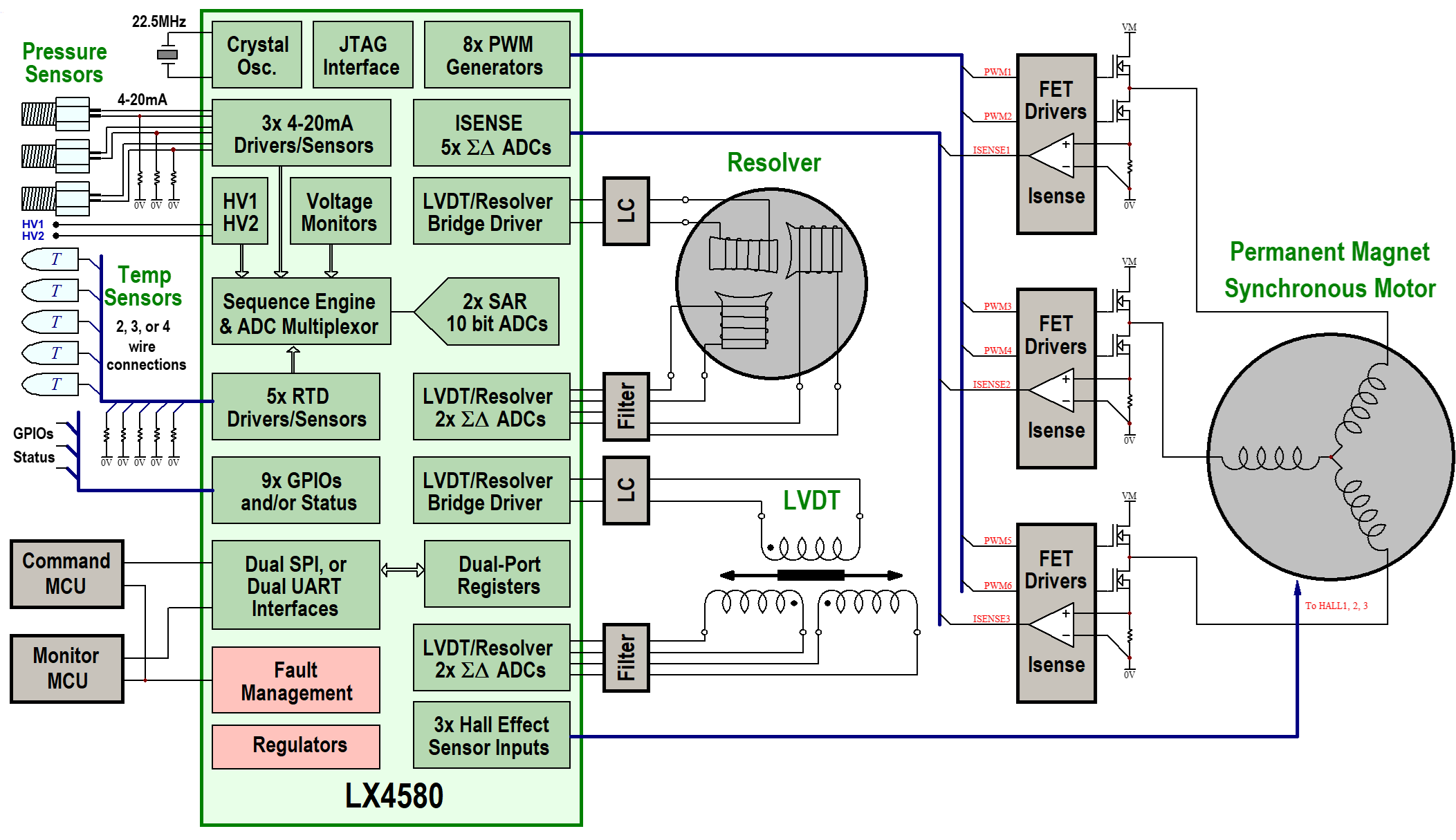
The block diagram below shows a typical motor-actuator system using a resolver to provide accurate Permanent Magnet Synchronous Motors (PMSM) rotor position, and a Linear Variable Differential Transformer (LVDT) for actuator linear position feedback. Motor current sensing and LVDT secondary waveform acquisition uses a dedicated Σ-Δ Analog-to-Digital Converter (ADC) per channel, nine in total. The LX4580 also includes sensor interfaces, which use a state machine and a pair of 10-bit SAR ADCs for digitizing. The topic of this article is to provide an overview of the LX4580's multiple supply rails and regulators and discuss regulator fault management. These blocks are shown in pink in the block diagram.
 |
Figure 1. Typical PMSM System
The LX4580 requires several external supply rails and generates several supply rails with internal low-drop-out (LDO) linear regulators, as shown in Table 1 below.
Table 1. Input Supply Rails
Rail |
Pins |
Supply Range |
Description |
VCC |
144 |
10V to 30V |
Analog high voltage supply, typically 15V |
VFB |
72 |
10V to 30V |
Resolver/LVDT primary drive supply, typically 15V |
VDD |
81, 110 |
2.25V to 5.5V |
Logic I/O supply, typically a nominal 2.5V, 3.3V, or 5V |
+5V_LDOs_IN to +5V_LDO_OUT, +5.25V_LDO_OUT |
141 |
6.2V to 17.5V |
Input to LX4580's internal 5V analog LDO, output at +5V_LDO_OUT |
Input to LX4580's internal 5.25V auxiliary LDO, output at +5.25V_LDO_OUT |
|||
+1.5VA_LDO_IN to +1.5VA_LDO_OUT |
132 |
1.85V to 5.5V |
Input to LX4580's internal 1.5VA analog core supply LDO, output at +1.5VA_LDO_OUT. +1.5VA_LDO_IN is normally connected to +5V_LDO_OUT |
+1.5VD_LDO_IN to +1.5VD |
122 |
1.85V to 5.5V |
Input to LX4580's internal 1.5VD digital core supply LDO, output at +1.5VD. +1.5VD_LDO_IN is normally connected to +5.25V_LDO_OUT |
The somewhat daunting collection of rails shown in Table 1 is easy to explain:
- The main analog supply, VCC, has a 10V to 30V operating range, and is usually selected to match the requirements of 4-20mA loop powered sensors. 15V is a common choice
- The VFB supply, again with a 10V to 30V operating range, is the supply rail for the LX4580's dual LVDT and/or resolver primary full-bridge drivers
- The analog data acquisition circuits use both 5V and 1.5V supplies, called +5V and +1.5VA. To keep these supplies low noise, they are provided by internal low drop-out regulators (LDOs). The 1.5VA regulator is normally driven by the output of the 5VA regulator
- External powered sensors which use a 5V supply can be operated from the output of an internal 5.25V LDO. The voltage is deliberately a little high to compensate for voltage drops across system wiring
- The internal logic uses a 1.5V core supply, +1.5VD, which uses a different LDO to the analog 1.5V supply to isolate digital noise from the analog circuits
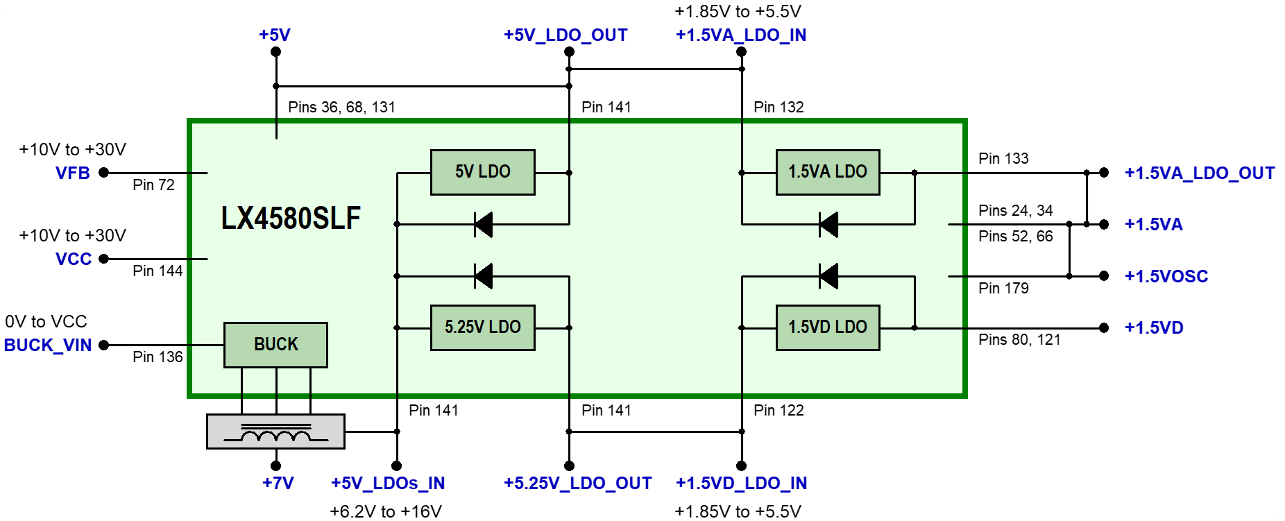
The 5V and 5.25V LDOs are supplied at a common input pin, +5V_LDOs_IN. Each LDO has an internal reverse-biassed diode from its output to the common input, so on power-down the 5V and 5.25V outputs will fall more or less together regardless of the relative loadings. The LX4580 also includes a buck regulator block, which will be discussed in detail in a subsequent article. The buck is intended to be used to pre-regulate VCC to a low voltage, such as 7V, as input to these two LDOs to reduce dissipation. The pre-regulator architecture is optional but is recommended to reduce LDO dissipation. This setup is shown below in block diagram form in Figure 2 below.
 |
Figure 2. Typical Power Supply Interconnections
LX4580 Supply Rail Fault Management
The LX4580 includes under- and over-voltage (UV/OV) detectors on power rails to detect out-of-specification conditions, plus over-temperature (OT) detection for the internal regulators. Power rail status is available in internal registers.
Failures of the VDD external logic supply, the 1.5VD internal logic supply or the clock source at OSC1 are deemed critical faults. Any one of these faults causes the LX4580 to shut down and restart to clear the unsafe condition.
Faults can be configured to put the LX4580 into the Safe Mode condition. The purpose of the Safe Mode is to set the outputs of LX4580 into a state that makes the system safe under certain, user chosen fault conditions. In this mode, all functional inputs and outputs are either high impedance or in another safe condition. However, the SPI or UART serial interfaces still operate in order to allow the host processor to diagnose the fault.
Transient under- or over-voltage faults on supplies are detected and latched as faults. Also, once a rail has gone out of range, a timer is started for that rail and should the fault continue for more than a programmable time, a further fault is latched. Any faults deemed critical can be masked to put the LX4580 into the Safe Mode condition.
If an over-temperature fault is detected on one of the four internal linear regulators, the regulator is cut off and restarts automatically when the temperature drops to a safe level. An OT fault occurrence is latched in internal registers, and individual regulator status can also be routed to GPIO pins if desired.
The LX4580 also reports a light load on the +5.25V supply (under a threshold in the 200µA to 2mA tolerance range), in the presumption that this means that the connection to external powered sensors has gone open.
Want More?
Check out the first, second and third posts from this series. For more information on the LX4580, visit our LX4580 web page or contact Dorian.Johnson@microchip.com.
