Overview of LX4580 Sensor Support and Sensor Fault Detection
Learn more about the LX4580 analog front-end Integrated Circuit (IC) for actuation systems and the capabilities of the sensor interfaces and fault detection.
High-Reliability LX4580 for Avionics Systems
The LX4580 is an analog front end for high-reliability motor-actuator control systems working under stringent standards such as DO-160 for avionics in airborne systems. The LX4580 interfaces with dual microcontrollers (MCUs) or Field-Programmable Gate Arrays (FPGAs) in redundant COM/MON system architectures, and features ECC encoding to provide 1 bit error correction and 2 bit error detection. Sequential logic is implemented with Triple Mode Redundancy (TMR) to protect against Single-Event Upsets (SEUs).
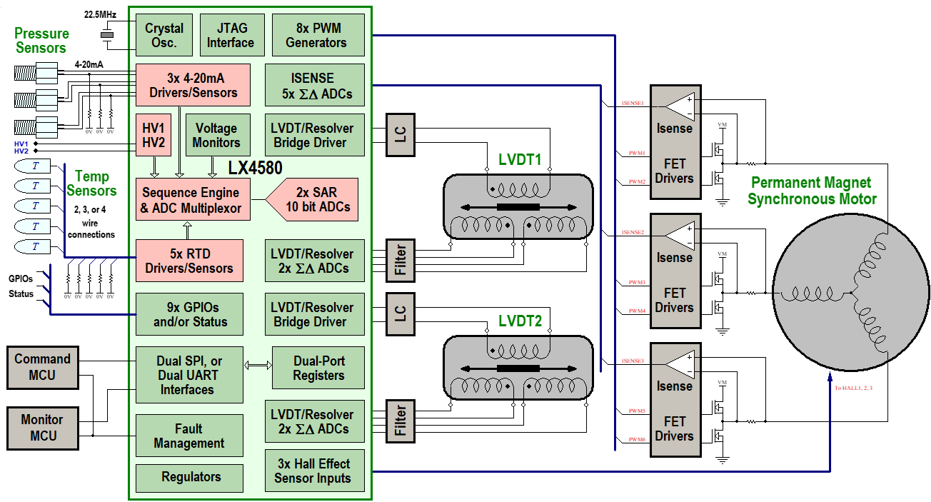
The block diagram below shows a typical Permanent Magnet Synchronous Motor (PMSM) motor-actuator system using redundant linear variable differential transformers (LVDTs) for actuator linear position feedback. The LX4580 combines analog sensor acquisition and motor control Pulse-Width Modulation (PWM) synthesis. Motor current sensing and LVDT secondary waveform acquisition uses a dedicated Σ-Δ ADC per channel, nine in total. The LX4580 also includes sensor interfaces, which use a state machine and a pair of 10-bit SAR Analog-to-Digital Converters (ADCs) for digitizing. These blocks are shown in pink in the block diagram. This is the third post of a series discussing topics around LX4580 implementations. The topic of this article is to provide an overview of the capabilities of the sensor interfaces and show how the dedicated analog front ends of each sensor interface assist in fault detection in external connections and the sensors themselves. Further articles will delve deeper into each sensor interface architecture.
 |
The LX4580 sensor interfaces are:
- Five independent temperature sensor interfaces configurable individually to suit Pt100 or Pt1000 type sensors
- Three independent 4-20mA current loop interfaces for any loop sensor, but typically used for pressure sensors
- Two general purpose single-ended analog input for voltage-output sensors or other monitoring
- Two LVDT/resolver interfaces, to be discussed as a separate topic
HV1 and HV2 General Purpose ADC Inputs
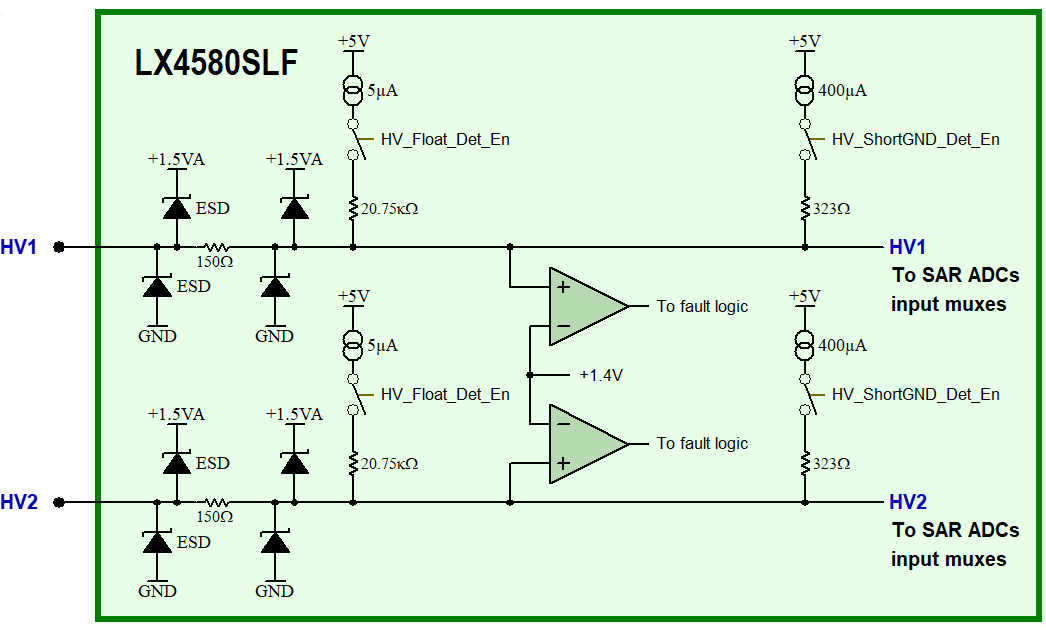
The simplest interfaces are two single ended inputs, HV1 and HV2, which have a 0V to 1.3V input range. The input structure is shown below:
 |
HV1 and HV2 General Purpose ADC Inputs Analog Front End
Each input includes fault testing for inputs either floating, shorted to GND or over-voltage. Fault detection uses current sources and comparators and operates as follows:
- Enabling the 5µA current sources tests for floating inputs
- An input is detected as floating if it can be pulled higher than 1.4V by 5µA, corresponding to a source resistance greater than 280kΩ
- Enabling the 400µA current sources tests for inputs shorted to GND
- An input is detected as shorted to GND if it cannot be pulled higher than 1.4V by 400µA, corresponding to a source resistance lower than 3.5kΩ
- With the current sources disabled, the comparators detect inputs that are naturally higher than 1.4V for over-voltage detection, since the expected input range is 0V to 1.3V
Temperature Sensor Interfaces
The LX4580 includes five independent temperature sensor interfaces, individually configurable to suit either Pt100 or Pt1000 type platinum temperature sensors. Temperature sensor connections can be 2, 3 or 4 wire as shown below:
 |
4-Wire, 3-Wire and 2-Wire
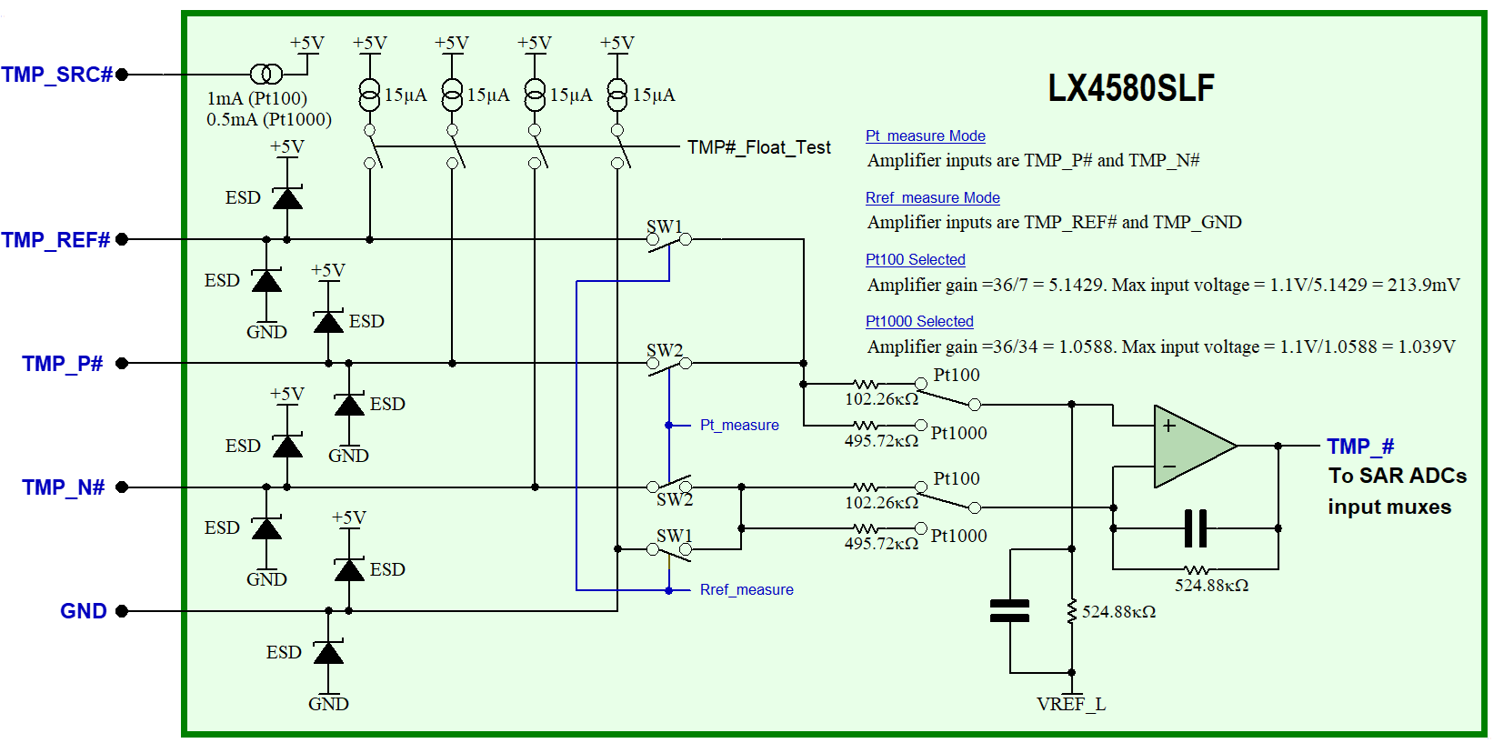
Each interface comprises a differential analog input between the TMP_P# and TMP_N# pins, a single-ended analog input between the TMP_REF# and GND pins and a current source at the TMP_SRC# pin for sensor excitation. The Pt100/ Pt1000 selection sets both the drive current and the ADC full scale input voltage. Since the same drive current passes through both the temperature sensor and an external precision reference resistor, RREF, the resistance of the temperature sensor is calculated by the ratio of the voltages across these two resistances.
The input structure is shown below. The switches route the voltage across either the temperature sensor or the external precision reference resistor to a differential amplifier:
 |
When a sensor interface is idle between ADC conversions, weak (15µA) current sources are switched to each of the input pins to check for open connections, detected by internal comparators. Other faults in either a Pt sensor or a reference resistor are detected by out of bounds ADC acquisition results.
4-20mA Current Loop (Pressure Sensor) Interfaces
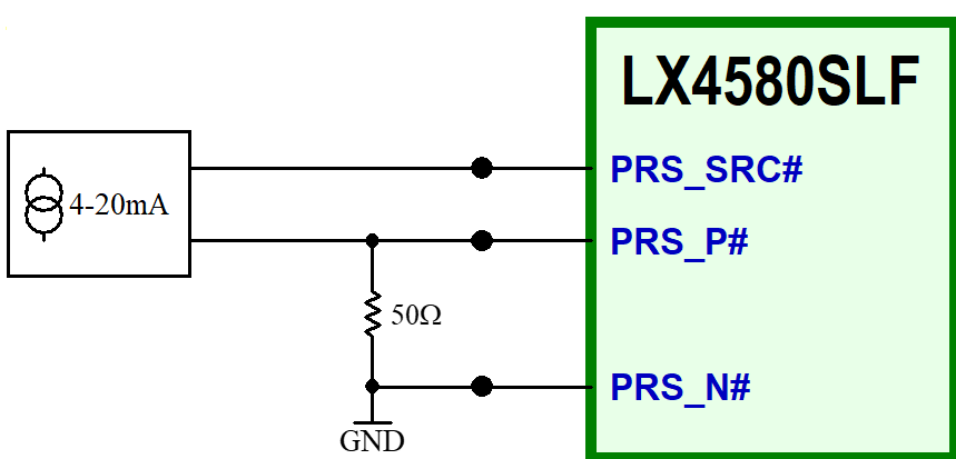
The LX4580 includes three independent 4-20mA current loop interfaces for typical pressure sensors. Each interface comprises a differential analog input between the PRS_P# and PRS_N# pins for current measurement and a power source at PRS_SRC# for sensor excitation as shown below:
 |
Using a 50Ω current sense resistor, the measurement range is 200mV to 1V for a 4-20mA loop current range. The input structure is shown below:
 |
Fault detection firstly involves protecting the power switch and checking that the sensor loop circuit itself is intact. The internal power switch is current limited to 30mA and includes an over-temperature cutoff to manage overload conditions including a shorted loop sensor. The voltage drop across the power switch can also be measured to check that the system is providing sufficient voltage to the loop sensor.
Faulty connections to the loop sensor between PRS_P# and PRS_N# are detected by a weak pullup current (5µA) on PRS_N# and a weak pulldown current (2.5µA) on PRS_P#. If either the loop itself or the connection to PRS_P# is broken, the weak pulldown on PRS_P# will cause an ADC value below the 200mV minimum expected for a working sensor. If the connection to PRS_N# is broken, the weak pullup on PRS_N# will again cause an ADC value below the 200mV minimum.
Want More?
Check out the first and second posts from this series. For more information, please visit our LX4580 web page.
