How to Select a Timer on AVR® MCUs
Read this post to learn more about different timer peripherals on AVR microcontrollers (MCUs) and how to select the best option for your application.
Exploring the Versatility of MCU Timers
Timers are a ubiquitous peripheral in microcontrollers (MCUs). It should come as no surprise that there are a lot of timers, each with their own pros and cons. Some timers are designed to be used as part of waveform generation, while others are ideal for pulse counting. In many cases, there is no wrong answer—it will depend on the requirements and resources available. This blog post is accurate to January 2024—new devices may introduce new features and timers that did not exist when this was written.
|
Width |
Measurement |
Waveform Generation |
Sleep Modes* |
TCA |
16-bit or 2x 8-bit |
Yes |
Yes |
Idle/Standby |
TCB |
16-bit |
Yes |
Yes |
Idle/Standby |
TCD |
12-bit |
Yes |
Yes |
Idle/Standby |
TCE |
16-bit |
Yes |
Yes |
Idle/Standby |
TCF |
24-bit |
No |
Yes |
Idle/Standby |
RTC |
16-bit |
No |
No |
Idle/Standby |
PIT |
16-bit |
No |
No |
Idle/Standby/Power-Down |
WDT |
N/A |
No |
No |
Idle/Standby/Power-Down |
*On AVR® MCUs, from most to least power, Idle → Standby → Power-Down.
Timer/Counter A (TCA)
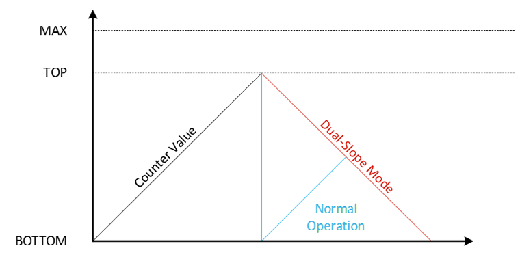
TCA is a timer optimized for generating Pulse Width Modulation (PWM). It can operate in 16-bit mode, for a high-resolution output, or 2x 8-bit mode, where each half of the timer operates independently. The counter runs until the TOP value is reached. When this occurs, the counter resets to the BOTTOM value (zero), except in dual-slope mode. In dual-slope mode, the counter does NOT reset to zero, but instead will count down to zero to reset the cycle. This is shown below in Figure 1.

Figure 1 – TCA Counter Behavior
To generate PWM, there are compare channels that check to see if the counter matches or exceeds the set value. If so, the output associated goes high. This timer also supports double buffering, where the values written to the counter are held until the timer triggers an update, which varies by operating mode. With the Event System (EVSYS), more advanced control is possible. For instance, the event system can be used to gate the input, count event edges, control the counting direction (up or down) and restart the timer during various conditions.
Timer/Counter B (TCB)
TCB is a 16-bit timer optimized for timing and capture. TCB can operate in a periodic interrupt mode, where an interrupt occurs at a constant interval. Time-out check mode is similar, except that the timer can be reset by an EVSYS input. TCB can also be operated as a single-shot timer. For long time periods, the RTC/PIT may be a better choice than TCB.
Capture modes refer to the ability of the timer to “capture” the count of the timer. This could be as simple as when an input occurs on a free-running timer, the length of time between two rising edges (frequency measurement) or the length of a pulse (pulse width measurement). Additionally, two TCBs can be used together to create a true 32-bit counter for high-precision measurements.
TCB can also be used as an 8-bit PWM generator, like single-slope mode in TCA.
Timer/Counter D (TCD)
TCD is a 12-bit timer optimized for generating complex PWM waveforms, such as half-bridge and full-bridge outputs. There are two comparators inside TCD: CMPA and CMPB. Each comparator has a SET value and a CLR value. When the count hits SET, the output is active. Then, when CLR is reached, the output is deactivated.
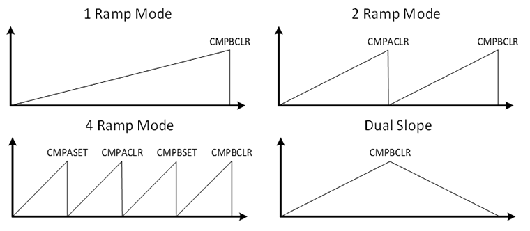
TCD supports four modes of operation: one ramp, two ramp, four ramp and dual slope. These names represent the number of cycles the counter goes through. Four ramp mode goes through four cycles, resetting on CMPASET, CMPACLR, CMPBSET and CMPBCLR, in that order. Two ramp mode goes through two cycles, resetting on CMPACLR and CMPBCLR, in that order. One ramp mode only resets on the CMPBCLR. Finally, dual slope mode counts up-to CMPBCLR then counts down to zero. For visual purposes, the graphic below has each ramp end at same y-position; however, they will vary when the values aren’t equal. Additionally, values not shown (e.g.: CMPASET in One Ramp mode) are still active, but do not play a role in the period.

Figure 2 – TCD Operating Modes
Through the event system, TCD also supports input blanking, digital filtering and several fault modes for clearing the output and/or suspending the count. TCD can also be used for input captures. Additionally, TCD can be used with the PLL (Phase Locked Loop) which enables TCD to operate at a frequency higher than the main clock.
Timer/Counter E (TCE) and Waveform Extension (WEX)
TCE is a 16-bit up-down timer optimized for timing and PWM generation. TCE is an up-down timer, meaning it can increment or decrement on each input, depending on the direction. When TCE reaches the TOP, the next value loaded depends on the direction at that point. If it is going up, then it rolls over to 0. If it is going down, TCE starts to decrement down to zero. Similarly, if the direction is down at this point, the counter rolls over to TOP, while a direction change to up makes the timer start incrementing.
To prevent timing glitches from occurring mid-timer cycle, TCE supports double-buffering, which loads the changed register values when a compare operation occurs. This allows the user to make changes while the timer is running.
TCE has multiple operating modes for generating waveforms. These modes are similar to the operating modes of the other timers. For instance, TCE supports “normal” timer operation, as well as single-slope PWM, dual-slope PWM and frequency generation. To improve the output resolution of PWM, the TCE has a high-resolution mode that can be used to improve the resolution of the PWM by using a high-speed clock signal. This signal should be at least 4x faster than the CPU speed for full utilization of this feature. TCE can utilize the PLL for generating the clock signal.
Additionally, the TCE also integrates with the WEX. The WEX allows the timer to generate complementary outputs, insert deadband time, create output patterns and handle fault signals in hardware.
Timer/Counter F (TCF)
TCF is a 24-bit timer optimized to act like a Numerically Controlled Oscillator (NCO). An NCO is a digital block comprised primarily of an accumulator, adder, and increment. Every clock cycle, a set increment is added to the accumulated total. When the accumulator overflows, the remainder is rolled over into the accumulator, and an output is generated. The PLL can be used with TCF, if equipped. Note: TCF runs asynchronously to the peripheral clock, which improves its flexibility; however, this leads to a delay when reading the timer count. Due to this, TCF is better used for frequency generation, rather than precise timekeeping.
In pulse frequency mode, the accumulator output is used to set the output, then a fixed (but user-set) number of clock cycles later, the output is cleared. In fixed duty cycle mode, the accumulator output signal toggles an output flip-flop, generating a 50% duty cycle.
Real Time Counter (RTC) and Periodic Interrupt Timer (PIT)
The RTC offers two timing functions: the Real Time Counter (RTC) and the Periodic Interrupt Timer (PIT). Both peripherals share the same clock source: either a 32.768 kHz external crystal, or an internal, ultra-low power 32.768 kHz oscillator, while operating independently of each other. When using a crystal oscillator, the RTC can correct for up to ±127 PPM of error. The clock source can be scaled down with a 15-bit prescaler.
The RTC can generate interrupts on a compare match and an overflow, while the PIT can generate an interrupt on a power-of-2 number of clock cycles (e.g., 2/4/8/…/32768). It should be noted that the RTC and PIT interrupts are not necessarily synchronous (i.e., will occur at the same time). The PIT should be used for ultra-low power applications, as it is the one of the only timers that continues to function all the way into power-down mode, while the RTC uses a little bit more power, but supports longer time periods. With a 1 Hz scaled clock, the RTC timeout period can be more than 18 hours.
Watchdog Timer (WDT)
The WDT is a special timer that will reset the microcontroller if it is not cleared periodically. It has multiple selectable time-out periods and runs from an internal 1.024 kHz oscillator derived from the internal, ultra-low power 32.768 kHz oscillator. The WDT has two modes—normal and windowed. In normal mode, the WDT must be cleared prior to the count matching. However, if somehow an error continuously clears the WDT, then the timer will not detect the fault. To protect against this possibility, window mode can be used.
In window mode, the WDT clear must occur after a set delay and before the timer triggers. If it is cleared too early or late, it will be considered a WDT violation, and will trigger a reset of the microcontroller. The WDT registers are protected by both the Configuration Change Protection (CCP) feature and the control register lock. This makes it difficult for SW errors to inadvertently change the WDT settings. The WDT operates in all power modes.
Selecting the Timer and Learning More
After understanding the timer peripherals, select which timer closest matches the features needed in the application. In many cases, there are multiple possible timers that can perform the task. In this case, select the simplest timer—this leaves timers with more capabilities available for future use. The device datasheet, application notes and technical briefs go into more detail on how all of these timers operate and the registers associated with them. Code examples that use a specific timer can be found by searching MPLAB Discover.
