Connecting an LX7720 to a Bipolar Stepper Motor
This blog is the 7th in a series that discusses the implementation aspects of the LX7720 spacecraft motor driver. It breaks down the LX7720's major functions into circuit blocks and sub-blocks and details how they work. This also explains the operation of sub-blocks and how they integrate into a motor drive system, helping designers to optimize their circuit designs.
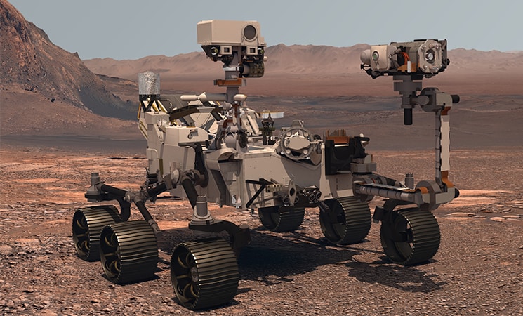
As space system developers continually work to reduce the size, weight and power of key modules and elements, they also require higher-performance, radiation-hardened and radiation-tolerant components that enhance system designs. New technology–such as lighter, more highly integrated motor control circuits for satellites–can withstand extreme space environments and optimize spacecraft performance.
The LX7720 spacecraft motor driver is radiation hardened by design. It’s a companion integrated circuit (IC) to a space Field Programmable Gate Array (FPGA) such as Microchip’s RTG4 FPGA and RT PolarFire® FPGA, or a space microcontroller (MCU) such as Microchip’s SAMRH71F20 or SAMV71Q21RT. The integrated current sensing, resolver, encoder, and Hall effect encoder interfaces in the LX7720 reduce board space and weight while increasing reliability for closed-loop motor control using coil current feedback and rotor position sensing.
This is the 7th blog in an eight-part series that focuses on LX7720's motor driver and current sense circuits, starting with the theory of the blocks within the FET driver and current sensing stages, followed by selection of external components, and finally practical implementation of brushless DC, bipolar and unipolar stepper motors. The topics in this series are:
- Introduction to the half-bridge drivers and discussion of the charge pump approach used to generate independent gate supplies for each high-side N-channel Field-Effect Transistor (NFET)
- Practical half-bridge driver stages using both standard gate voltage and low gate voltage NFETs
- Introduction to the motor winding current sense amplifiers
- Topology choices applying current sense amplifiers within a half-bridge stage
- Separating a half-bridge into independent low-side and high-side drivers
- Connecting an LX7720 to a Brushless DC Motor (BLDC) or Permanent Magnet Synchronous Motor (PMSM), with optional electromagnetic brake
- Connecting an LX7720 to a bipolar stepper motor
- Connecting an LX7720 to one or two unipolar stepper motors
The LX7720 contains four half-bridge drivers with floating current sense for motor coil driving, six bi-level inputs (comparators) for sensing Hall effect sensors and rotary encoders, and a complete resolver/LVDT interface with primary coil driver and secondary signal conditioning. Figure 1 shows a top-level block diagram for typical motor drive system using the LX7720 and illustrates the benefit of integrating all the mixed-signal electronics for a closed loop motor driver within one IC.
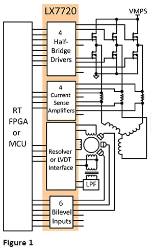
Figure 1. Typical Motor Drive System using LX7720
The first blogs discussed the fundamentals of the LX7720's half-bridge stages and integrated current sensing. The previous blog discussed using the LX7720 with PMSM and Permanent Magnet Synchronous Motors (BLDC) . This blog discusses using the LX7720 with bipolar stepper motors.
The LX7720 contains four half-bridge driver stages and four current sense amplifiers, which is enough to drive a two-phase bipolar stepper motor.
Figure 2 shows a generic two-phase bipolar stepper motor being driven by four half-bridge drivers operating in pairs as two H-bridges. The LX7720 circuitry is shown simplified, with supplies and decoupling to the current sense and gate drive sections omitted. The key components are the four half-bridges and the current sense.
The architecture shown here uses a single current sense per winding, in series with the common ground path for each H-bridge. Each H-bridge has bi-directional current sensing in one of its half-bridge outputs. Current entering one half-bridge from the VMPS motor supply will exit via the other half-bridge, and a positive voltage will develop across the current sense resistor proportional to this current. Since current entering one half-bridge has to exit via another half-bridge, only two current senses are needed.
The half-bridge FETs are shown with their integral body diodes. Diodes in parallel with the FETs are necessary components to carry commutation currents when a half-bridge FET switches off. Commutation current flow after FET switch-off is discussed in the 4th blog. The FET body diodes are often paralleled by discrete diodes for higher switching speed and lower voltage drop. Motor winding currents normally flow in through a high-side FET from the motor supply VMPS, and out to the motor ground MGND through a low-side FET. During commutation when the FETs are off, current will be carried by diodes in parallel with the FETs.
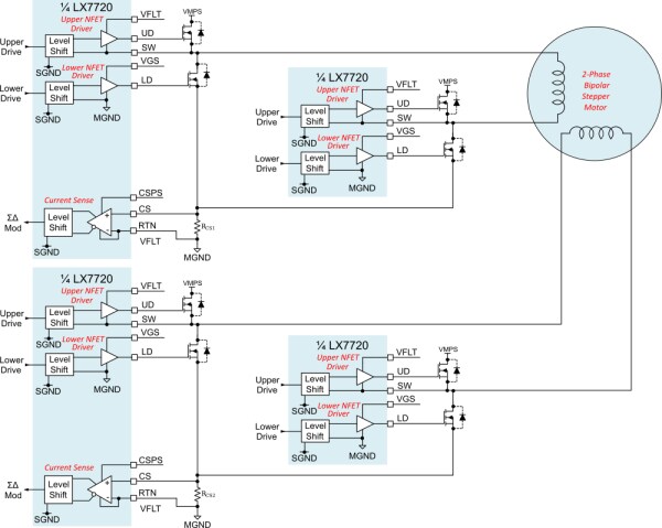
Figure 2. 2-Phase Bipolar Stepper Motor Driver with Ground-Side Current Sensing
An alternative current sensing architecture relocates the current sensing to be at one side of each H-bridge's drive output. Again, since current entering one half-bridge has to exit via another half-bridge, only two current senses are needed. However, including the additional current sense circuits provides redundancy, if required. Figure 3 shows the two unused current sense stages' pins tied to ground.
The current sensing is now bidirectional, depending whether the half-bridge with the current sense is sourcing current or sinking current.

Figure 3. 2-Phase Bipolar Stepper Motor Driver with Phase Output Current Sensing
The LX7720 uses two internal ground domains, shown in Figure 3 as the signal ground SGND, and the motor ground MGND. SGND is used for the digital and analog signals (the control circuitry). MGND is used for circuitry associated with the external half-bridges - the FET drives, current sensing, and the motor load itself. The level shifters manage the crossing of the GND domains. In most applications, the two grounds SGND and MGND are joined together directly on the PCB. The 6th blog discusses the ground domains in detail, particularly for high power motor designs where the power switching components are on a separate module or PCB.
Synchronous motors are also available with more than two phase windings. Since the half-bridge and current sense stages are independent within an LX7720, multiple LX7720s can be used together to control a motor with more than two phases.
You should now understand how to connect an LX7720 to a bipolar stepper motor. The next blog in this series will discuss connecting an LX7720 to unipolar stepper motors.
Learn more about the LX7720 and other radiation-hardened mixed signal ICs.
Read other parts of this series:
Part 2: Practical half-bridge driver stages using both standard gate voltage and low gate voltage NFETs
Part 3: Introduction to the motor winding current sense amplifiers
Part 4: Topology choices applying current sense amplifiers within a half-bridge stage
Part 5: Separating a half-bridge into independent low-side and high-side drivers
Part 8: Connecting an LX7720 to one or two unipolar stepper motors