Using the LX7720's Motor Drivers - Part 5: Separating a Half-Bridge into Independent Low-Side and High-Side Drivers
This article is the 5th in a series that discusses the implementation aspects of the LX7720 spacecraft motor driver. It breaks down the LX7720's major functions into circuit blocks and sub-blocks and details how they work. This also explains the operation of sub-blocks and how they integrate into a motor drive system, helping designers to optimize their circuit designs.
As space system developers continually work to reduce the size, weight and power of key modules and elements, they also require higher-performance, radiation-hardened and radiation-tolerant components that enhance system designs. New technology–such as lighter, more highly integrated motor control circuits for satellites–can withstand extreme space environments and optimize spacecraft performance.
The LX7720 spacecraft motor driver is radiation hardened by design. It’s a companion integrated circuit (IC) to a space Field Programmable Gate Array (FPGA) such as Microchip’s RTG4 FPGA and RT PolarFire® FPGA, or a space microcontroller (MCU) such as Microchip’s SAMRH71F20 or SAMV71Q21RT. The integrated current sensing, resolver, encoder, and Hall effect encoder interfaces in the LX7720 reduce board space and weight while increasing reliability for closed-loop motor control using coil current feedback and rotor position sensing.
This is the fifth article in an eight-part series that focuses on LX7720's motor driver and current sense circuits, starting with the theory of the blocks within the FET driver and current sensing stages, followed by selection of external components, and finally practical implementation of brushless DC, bipolar and unipolar stepper motors. The topics in this series are:
1. Introduction to the half-bridge drivers and discussion of the charge pump approach used to generate independent gate supplies for each high-side N-channel Field-Effect Transistor (NFET)
2. Practical half-bridge driver stages using both standard gate voltage and low gate voltage NFETs
3. Introduction to the motor winding current sense amplifiers
4. Topology choices applying current sense amplifiers within a half-bridge stage
5. Separating a half-bridge into independent low-side and high-side drivers
6. Connecting an LX7720 to a Brushless DC Motor (BLDC) or Permanent Magnet Synchronous Machine (PMSM), with optional electromagnetic brake
7. Connecting an LX7720 to a bipolar stepper motor
8. Connecting an LX7720 to one or two unipolar stepper motors
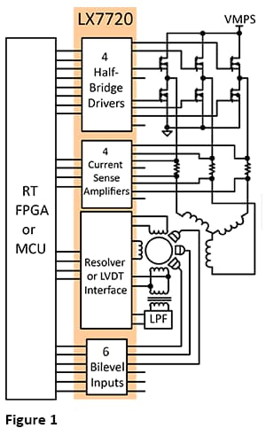
The LX7720 contains four half-bridge drivers with floating current sense for motor coil driving, six bi-level inputs (comparators) for sensing Hall effect sensors and rotary encoders, and a complete resolver/LVDT interface with primary coil driver and secondary signal conditioning. Figure 1 shows a top-level block diagram for typical motor drive system using the LX7720 and illustrates the benefit of integrating all the mixed-signal electronics for a closed loop motor driver within one IC.
This article discusses separating half-bridges into independent low-side and high-side drivers.
The LX7720 contains four half-bridge driver stages and four current sense amplifiers. This previous article discussed the ways to set up a current measurement with a half-bridge stage: ground-side sensing, motor supply-side sensing, and motor drive output sensing. This article discusses separating a half-bridge into independent low-side and high-side drivers, and how to use current sensing in these cases.
Each of the four half-bridge driver stages contains an individual high-side and low-side NFET driver. In normal use, the combination of a high-side and low-side NFET driver is used as a pair to form a half-bridge. However, since the LX7720's high-side and low-side drivers have independent control signals, the drivers can be used independently. This can be useful for three-phase motor driver applications, because the fourth half-bridge is often spare, and can be used for independent high-side and low-side power switches.
Figure 2 and Figure 3 show a half-bridge driver split into independent high-side and low-side NFET drivers without current sensing.
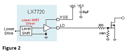
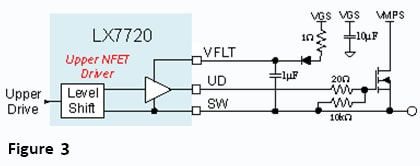
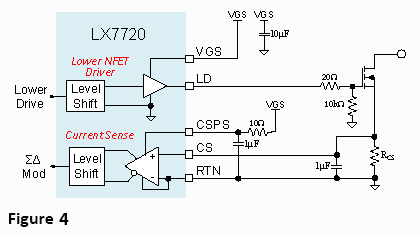
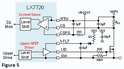
Figure 4 and Figure 5 show the same low-side and high-side drivers, but with current sensing applied. These circuits are the same as the complete half-bridge circuits discussed in our fourth article, but with only one driver stage and external NFET.
The current sense resistor for the low-side driver will develop a positive voltage proportional to sink current when the lower NFET is on (Figure 4).
The current sense resistor for the high-side driver will develop a negative voltage proportional to source current when the upper NFET is on (Figure 5).
Now, a couple of caveats to keep in mind. First, there is only one current sense circuit per half-bridge stage, so it can be assigned to the high-side switch or to the low-side load switch, but not to both. Second, the VGS gate supply and VMPS motor supply are common to all four half-bridges. This means that a standalone high-side switch can only be used to switch the VPMS supply.
Section 5: Next Steps — Conclusion
You should now understand how to separate a half-bridge into independent low-side and high-side drivers. The next article in this series will discuss connecting an LX7720 to a Brushless DC Motor (BLDC) or Permanent Magnet Synchronous Machine (PMSM), with optional electromagnetic brake.
Learn more about the LX7720 and other radiation-hardened mixed signal ICs.
Read other parts of this series:
Part 2: Practical half-bridge driver stages using both standard gate voltage and low gate voltage NFETs
Part 3: Introduction to the motor winding current sense amplifiers
Part 4: Topology choices applying current sense amplifiers within a half-bridge stage
Part 7: Connecting an LX7720 to a bipolar stepper motor
Part 8: Connecting an LX7720 to one or two unipolar stepper motors