
Using the LX7720's Motor Drivers - Part 3: Introduction to the Motor Winding Current Sense Amplifiers
This article is the third in a series that discusses implementation aspects of the LX7720 spacecraft motor driver. It breaks down the LX7720's major functions into circuit blocks and sub-blocks and details how they work. This also explains the operation of sub-blocks and how they integrate into a motor drive system, helping designers to optimize their circuit designs.
As space system developers continually work to reduce the size, weight and power of key modules and elements, simultaneously they require higher-performance, radiation-hardened and radiation-tolerant components that enhance system designs. New technology – such as lighter, more highly integrated motor control circuits for satellites – can withstand extreme space environments and optimize spacecraft performance.
The LX7720 spacecraft motor driver is radiation hardened by design. It’s a companion integrated circuit (IC) to a space Field Programmable Gate Array (FPGA) such as Microchip’s RTG4 FPGA and RT PolarFire® FPGA, or a space microcontroller (MCU) such as Microchip’s SAMRH71F20 or SAMV71Q21RT. The integrated current sensing, resolver, encoder and Hall effect encoder interfaces in the LX7720 reduce board space and weight while increasing reliability for closed-loop motor control using coil current feedback and rotor position sensing.
This is the third article in an eight-part series that focuses on LX7720's motor driver and current sense circuits, starting with the theory of the blocks within the FET driver and current sensing stages, followed by selection of external components, and finally practical implementation of brushless DC, bipolar and unipolar stepper motors. The topics in this series are:
1. Introduction to the half-bridge drivers and discussion of the charge pump approach used to generate independent gate supplies for each high-side N-channel Field-Effect Transistor (NFET)
2. Practical half-bridge driver stages using both standard gate voltage and low gate voltage NFETs
3. Introduction to the motor winding current sense amplifiers
4. Topology choices applying current sense amplifiers within a half-bridge stage
5. Separating a half-bridge into independent low-side and high-side drivers
6. Connecting an LX7720 to a Brushless DC Motor (BLDC) or Permanent Magnet Synchronous Machine (PMSM), with optional electromagnetic brake
7. Connecting an LX7720 to a bipolar stepper motor
8. Connecting an LX7720 to one or two unipolar stepper motors
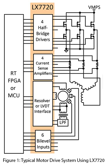
The LX7720 contains four half-bridge drivers with floating current sense for motor coil driving, six bi-level inputs (comparators) for sensing Hall effect sensors and rotary encoders, and a complete resolver/LVDT interface with primary coil driver and secondary signal conditioning. Figure 1 shows a top-level block diagram for typical motor drive system using the LX7720 and illustrates the benefit of integrating all the mixed-signal electronics for a closed-loop motor driver within one IC.
This article introduces the motor winding current sense amplifiers.
Introduction to the Motor Winding Current Sense Amplifiers
Each of the four half-bridge FET driver stages includes an amplifier intended for current sensing by monitoring the voltage across an external current sense resistor. The sense voltage range is ±200 mV, and therefore either uni-directional or bi-directional current can be measured. The current sense amplifiers can be used for other low-voltage measurement purposes since they are independent from the NFET drivers.
Each current sense amplifier has an independent current sense power supply rail, CSPS, with the same 10V to 18V allowed voltage range as the VGS gate drive supply. Current sensing can be configured in either the motor supply, the motor ground, or a half-bridge output, depending on the CSPS connections.
Figure 2 shows the current sense block, with resistor/capacitor (RC) decoupling for the supply pin, CSPS, and the current sense resistor RCS. The RTN pin is both the inverting current sense input and the amplifier supply ground.

Conclusion
You should now understand the current sense amplifiers as a circuit block. The next article in this series will discuss three alternative methods of applying current measurement to a half-bridge stage using the current sense amplifier introduced here.
Learn more about the LX7720 and other radiation-hardened mixed signal ICs.
Read other parts of this series:
Part 2: Practical half-bridge driver stages using both standard gate voltage and low gate voltage NFETs
Part 4: Topology choices applying current sense amplifiers within a half-bridge stage
Part 5: Separating a half-bridge into independent low-side and high-side drivers
Part 7: Connecting an LX7720 to a bipolar stepper motor
Part 8: Connecting an LX7720 to one or two unipolar stepper motors
Connect with Dorian Johnson on LinkedIn.