Using the LX7720 Motor Drivers - Part 4: Performing Current Measurements Within the Half-Bridge Stage
This article is the fourth in a series that discusses implementation aspects of the LX7720 spacecraft motor driver. It breaks down the LX7720's major functions into circuit blocks and sub-blocks and details how they work. This also explains the operation of sub-blocks and how they integrate into a motor drive system, helping designers to optimize their circuit designs.
As space system developers continually work to reduce the size, weight and power of key modules and elements, they also require higher-performance, radiation-hardened and radiation-tolerant components that enhance system designs. New technology – such as lighter, more highly integrated motor control circuits for satellites – can withstand extreme space environments and optimize spacecraft performance.
The LX7720 spacecraft motor driver is radiation hardened by design. It’s a companion integrated circuit (IC) to a space Field Programmable Gate Array (FPGA) such as Microchip’s RTG4 FPGA and RT PolarFire® FPGA, or a space microcontroller (MCU) such as Microchip’s SAMRH71F20 or SAMV71Q21RT. The integrated current sensing, resolver, encoder, and Hall effect encoder interfaces in the LX7720 reduce board space and weight while increasing reliability for closed-loop motor control using coil current feedback and rotor position sensing.
This is the fourth article in an eight-part series that focuses on the LX7720's motor driver and current sense circuits, starting with the theory of the blocks within the FET driver and current sensing stages, followed by selection of external components, and finally practical implementation of brushless DC, bipolar and unipolar stepper motors. The topics in this series are:
- Introduction to the half-bridge drivers and discussion of the charge pump approach used to generate independent gate supplies for each high-side N-channel Field-Effect Transistor (NFET)
- Practical half-bridge driver stages using both standard gate voltage and low gate voltage NFETs
- Introduction to the motor winding current sense amplifiers
- Topology choices for applying current sense amplifiers within a half-bridge stage
- Separating a half-bridge into independent low-side and high-side drivers
- Connecting an LX7720 to a Brushless DC Motor (BLDC) or Permanent Magnet Synchronous Machine (PMSM), with optional electromagnetic brake
- Connecting an LX7720 to a bipolar stepper motor
- Connecting an LX7720 to one or two unipolar stepper motors
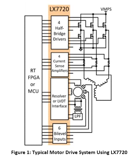
The LX7720 contains four half-bridge drivers with floating current sense for motor coil driving, six bi-level inputs (comparators) for sensing Hall effect sensors and rotary encoders, and a complete resolver/LVDT interface with primary coil driver and secondary signal conditioning. Figure 1 shows a top-level block diagram for typical motor drive system using the LX7720 and illustrates the benefit of integrating all the mixed-signal electronics for a closed loop motor driver within one IC.
This article discusses topology choices for applying a current sense amplifier within a half-bridge stage.
The LX7720 contains four half-bridge driver stages and four current sense amplifiers. The various methods for performing current measurements in a half-bridge stage using one of the built-in current sense amplifiers are discussed below.
There are three ways to set up a current measurement with a half-bridge stage: Ground-side sensing (Figure 2), motor supply-side sensing (Figure 3), and motor drive output sensing (Figure 4). The difference between the topologies is where the current sense resistor is placed and how CSPS, CS and RTN are connected. In all three cases, the CSPS supply rail is either directly connected to or derived from the VGS supply.
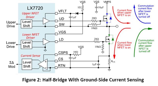
Half-bridge with Ground-side Current Sensing
Figure 2 shows a complete half-bridge stage with a current measurement taken in the source leg of the lower NFET.
The current sense amplifier is powered from VGS and decoupled with an RC filter. The current sense resistor will develop a positive voltage proportional to the sink current when the lower NFET is on. When the lower NFET is turned off, the commutation current sunk from an inductive load will ramp down through the upper NFET's body diode into the VMPS motor supply as shown below in blue.
Current flow sourced through the upper NFET into the load will not be measured. If the upper and lower NFETs' on times overlap (avoid this!), the shoot-through current will be detected because it will pass through the current sense resistor. Also, when the upper NFET is turned off, the commutation current to any inductive load will ramp down through the lower NFET's body diode, as shown below in green. The current sense resistor will develop a negative voltage proportional to the commutation current. The sense voltage range is ±200mV, so this reverse current flow will be measured.
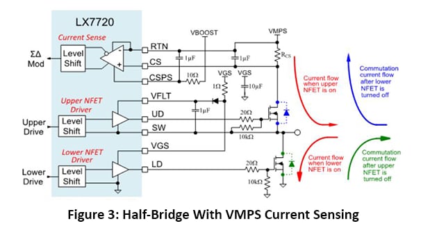
Half-Bridge with VMPS Current Sensing
Figure 3 shows a complete half-bridge stage with the current measurement in the drain leg of the upper NFET.
The current sense amplifier is powered between VBOOST and VMPS (so above VMPS) and is decoupled with an RC filter. The current sense resistor will develop a negative voltage proportional to the source current when the upper NFET is on. When the upper NFET is turned off, the commutation current sunk from an inductive load will ramp down through the lower NFET's body diode into the VMPS motor supply as shown below in green.
Current flow sourced through the lower NFET into the load will not be measured. If the upper and lower NFETs' on times overlap, the shoot-through current will be detected because it will pass through the current sense resistor. Also, when the lower NFET is turned off, the commutation current to any inductive load will ramp down through the upper NFET's body diode as shown below in blue. The current sense resistor will develop a positive voltage proportional to the commutation current.
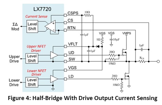
Half-bridge with Drive Output Current Sensing
Figure 4 shows a complete half-bridge stage with current measurement in the drive output.
The current sense amplifier is powered by the upper driver's VFLT floating supply and is decoupled with an RC filter. VFLT floats relative to the SW pin, so the current sense amplifier's RTN supply and inverting input is therefore connected to the SW pin. The current sense resistor will develop a negative voltage proportional to the current sourced from the half-bridge and a positive voltage proportional to the current sunk by the half-bridge.
Conclusion
You should now understand the three methods of applying current measurement to a half-bridge stage. The next blog in this series will discuss separating a half-bridge into independent low-side and high-side drivers.
Learn more about the LX7720 and other radiation-hardened mixed signal ICs.
Read other parts of this series:
Part 2: Practical half-bridge driver stages using both standard gate voltage and low gate voltage NFETs
Part 3: Introduction to the motor winding current sense amplifiers
Part 5: Separating a half-bridge into independent low-side and high-side drivers
Part 7: Connecting an LX7720 to a bipolar stepper motor
Part 8: Connecting an LX7720 to one or two unipolar stepper motors
Connect with Dorian Johnson on LinkedIn.