Using the LX7720's Motor Drivers - Part 2: Implementing a Half-bridge Driver with Standard or Low-voltage NFETs
This article is the second in a series that discusses implementation aspects of the LX7720 spacecraft motor driver. It breaks down the LX7720's major functions into circuit blocks and sub-blocks and details how they work. This also explains the operation of sub-blocks and how they integrate into a motor drive system, helping designers to optimize their circuit designs.
As space system developers continually work to reduce the size, weight and power of key modules and elements, simultaneously they require higher-performance, radiation-hardened and radiation-tolerant components that enhance system designs. New technology – lighter, more highly integrated motor control circuits for satellites – can withstand extreme space environments and optimize spacecraft performance.
The LX7720 spacecraft motor driver is radiation hardened by design. It’s a companion integrated circuit (IC) to a space FPGA such as Microchip’s RTG4 FPGA and RT PolarFire® FPGA, or a space microcontroller (MCU) such as Microchip’s SAMRH71F20 or SAMV71Q21RT. The integrated current sensing, resolver, encoder and Hall encoder interfaces reduce board space and weight while increasing reliability for closed-loop motor controllers using coil current feedback and rotor position sensing.
This is the second blog in an eight-part series that focuses on LX7720's motor driver and current sense circuits, starting with the theory of the blocks within the FET driver and current sensing stages, followed by a selection of external components, and finally practical implementation of brushless DC, bipolar and unipolar stepper motors.
The topics in this series are:
- Introduction to the half-bridge drivers and discussion of the charge pump approach used to generate independent gate supplies for each high-side N-channel Field-Effect Transistor (NFET)
- Practical half-bridge driver stages using both standard gate voltage and low gate voltage NFETs
- Introduction to the motor winding current sense amplifiers
- Topology choices applying current sense amplifiers within a half-bridge stage
- Separating a half-bridge into independent low-side and high-side drivers
- Connecting an LX7720 to a Brushless DC Motor (BLDC) or Permanent Magnet Synchronous Machine (PMSM), with optional electromagnetic brake
- Connecting an LX7720 to a bipolar stepper motor
- Connecting an LX7720 to one or two unipolar stepper motors
Half-bridge Driver Stages Using Standard Gate Voltage and Low Gate Voltage NFETs
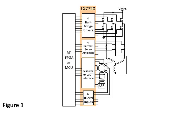
The LX7720 contains four half-bridge drivers with floating current sense for motor coil driving, six bi-level inputs (comparators) for sensing Hall effect sensors and rotary encoders, and a complete resolver/LVDT interface with primary coil driver and secondary signal conditioning. Figure 1 shows a top-level block diagram for a typical motor drive system using LX7720, and illustrates the benefit of integrating all the mixed-signal electronics for a closed-loop motor driver within one IC.
See Figure 1: Typical Motor Drive System Using LX7720
Half-bridge Stage Using High Gate-Voltage NFETs
The LX7720 uses a 10V to 18V VGS gate drive supply for compatibility with conventional high gate voltage NFETs. These devices are turned on hard with an 8V to 12V gate voltage and usually have a VGS(max) in the range ±20Ω to ±30Ω. Figure 2 shows an example half-bridge stage with typical component values.
The diodes with dotted lines are the MOSFETs' integral body diodes. The body diodes are usually rated to carry the same current as the MOSFET itself and can be used to recirculate inductive load currents during commutation. External diodes are preferred because they can be faster and have a lower forward voltage.
The 20Ω resistors in series with the gates are nominal values that form an RC network together with the gate capacitance to provide turn-on and turn-off slew limiting control. Optionally fit the diode shown in parallel with each 20Ω resistor to set slew limiting during NFET turn-on but retain fast turn-off. The 10kΩ gate-source resistors ensure that the NFETs are off when the FET drivers are at high impedance.
See Figure 2: Half-bridge with High Gate Voltage NMOS FETs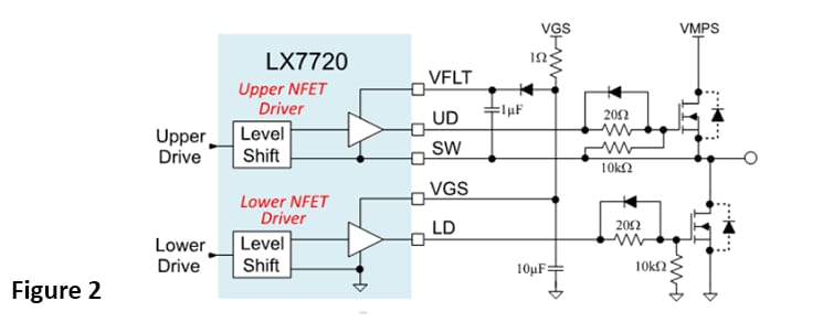
Half-bridge Stage Using Low Gate-Voltage NFETs
The 10V LX7720 VGS supply minimum is too high for many low threshold MOSFETs and enhancement mode GaN FETs. Figure 3 shows an example half-bridge stage with typical component values using low threshold MOSFETs with VGS(max)=6V. Here, the maximum gate drive is limited to nominally 4.3V with a Zener diode. Per the LX7720 Operating Ratings, the limit for each FET driver's average source/sink current is 25mA. Here, the 470Ω series resistor limits the continuous current when the average source/sink current is 25mA. Here, the 470W series resistor limits the continuous current when a FET driver is high to about: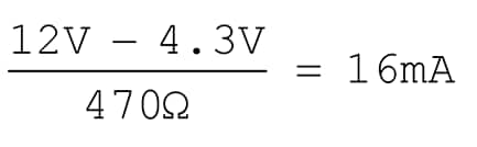
An optional speed-up capacitor across the 470Ω resistor can be used to help balance the NFET's gate-charge and speed up the NFET's initial turn-on to the Miller plateau. The balancing speed-up capacitance, CSU, is set by: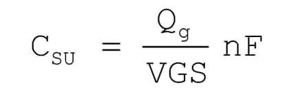
where Qg is the NFET's specified typical gate-source charge in nC. For example, using a 12V VGS supply voltage and NFETs with a 12nC typical gate-source charge gives: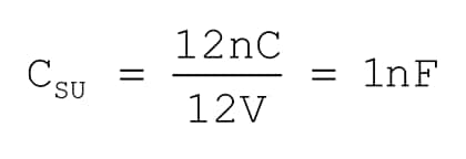
See Figure 3: Half-bridge with Low Gate Voltage NMOS or GaN FETs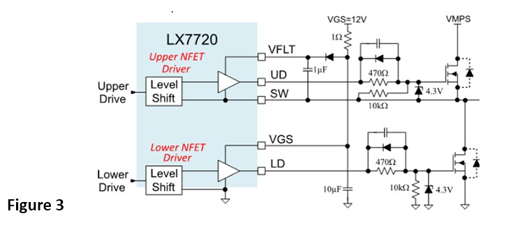
You should now understand the LX7720 practical half-bridge driver stages and the use of the standard gate voltage and low gate voltage NFETs. The next article in this series will introduce the motor winding current sense amplifiers
Learn more about the LX7720 and other radiation-hardened mixed signal ICs.
Read other parts of this series:
Part 3: Introduction to the motor winding current sense amplifiers
Part 4: Topology choices applying current sense amplifiers within a half-bridge stage
Part 5: Separating a half-bridge into independent low-side and high-side drivers
Part 7: Connecting an LX7720 to a bipolar stepper motor
Part 8: Connecting an LX7720 to one or two unipolar stepper motors