Using the LX7720's Motor Drivers - Part 1: Introduction to the Half-bridge Driver
This article is the first in a series that discusses the implementation aspects of the LX7720 spacecraft motor driver. It breaks down the LX7720's major functions into circuit blocks and sub-blocks and details how they work. This also explains the operation of sub-blocks and how they integrate into a motor drive system, helping designers to optimize their circuit designs.
The LX7720 is a spacecraft motor driver that is radiation hardened by design. It is a companion IC to a space FPGA, such as Microchip’s RTG4 FPGA and RT PolarFire® FPGA, or a space microcontroller (MCU), such as Microchip’s SAMRH71F20 or SAMV71Q21RT. The integrated current sensing, resolver, encoder and Hall encoder interfaces reduce board space and weight while increasing reliability for closed loop motor controllers using coil current feedback and rotor position sensing.
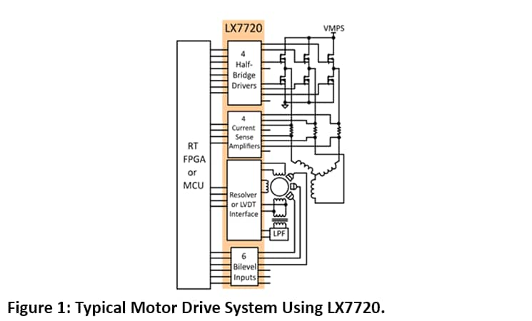
The LX7720 contains four half-bridge drivers with floating current sense for motor coil driving, six bi-level inputs (comparators) for sensing Hall effect sensors and rotary encoders, and a complete resolver/LVDT interface with primary coil driver and secondary signal conditioning. Figure 1 shows a top level block diagram for typical motor drive system using LX7720, and illustrates the benefit of integrating all the mixed-signal electronics for a closed loop motor driver within one IC.
This is the first in a eight-part series that focuses on LX7720's motor driver and current sense circuits, starting with the theory of the blocks within the FET driver and current sensing stages, followed by selection of external components, and finally practical implementation of brushless DC, bipolar and unipolar stepper motors. The subjects for each part of the series are as follows:
• Introduction to the half-bridge drivers and discussion of the charge pump approach used to generate independent gate supplies for each high-side N-channel Field-Effect Transistor (NFET)
• Practical half-bridge driver stages using both standard gate voltage and low gate voltage NFETs
• Introduction to the motor winding current sense amplifiers
• Topology choices applying current sense amplifiers within a half-bridge stage
• Separating a half-bridge into independent low-side and high-side drivers
• Connecting an LX7720 to a Brushless DC Motor (BLDC) or Permanent Magnet Synchronous Machine (PMSM), with optional electromagnetic brake
• Connecting an LX7720 to a bipolar stepper motor
• Connecting an LX7720 to one or two unipolar stepper motors
This first article introduces the half-bridge motor driver stages and the high-side NFET charge pump.
Half-bridge Motor Driver Stages
The LX7720 contains four half-bridge driver stages. The essentials of a half-bridge stage are shown in figure 1 below, with the current sense circuitry omitted. The VGS rail is an externally supplied 10V to 18V gate drive supply, which is used directly to drive the lower NFET. The lower drive (LD) gate drive output swings between VGS and motor ground.
The lower and upper drives are independent, although they are typically used together to form a half bridge. If an LX7720 is used to drive a 3-phase motor, only three half-bridges are needed. The remaining half-bridge can be used as an independent high-side power switch plus an independent low-side power switch.
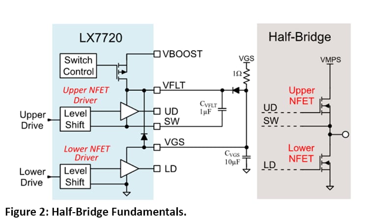
The upper external FET is also an NFET, so each driver generates a floating high-side supply, VFLT, for the upper NFET's gate driver. The upper drive (UD) gate output swings between VFLT and SW, with SW being connected to the upper NFET's source (also the power stage's output). VFLT needs to swing from ground (when the upper NFET is off) to above the VMPS motor supply (upper NFET is fully on), following the voltage on SW.
VFLT is supplied two ways. Firstly, capacitor CVFLT charges up to VGS whenever SW is grounded. When the upper NFET is off, the current flow is through the load if the upper NFET is being used stand-alone as a high-side switch. In the case of a half-bridge, the current flow can be through the load or through the bottom NFET (when on). If the upper drive is used as an independent high-side power switch, the grounded external load provides the charging path for CVFLT. The external 1W resistor constrains the peak charging current into CVFLT, which is usually a low-ESR chip ceramic component. The external diode is in parallel with the internal diode shown and keeps the peak charging current off-chip.
When the UD gate drive output goes high, the CVFLT capacitor maintains VFLT during the upper NFET's turn-on transition. A charge pump, Figure 2, generates a high-side supply, VBOOST, which is a little less than VGS volts above the motor supply, VMPS. VBOOST is used to restore the voltage on CVFLT during an upper NFET's on-time.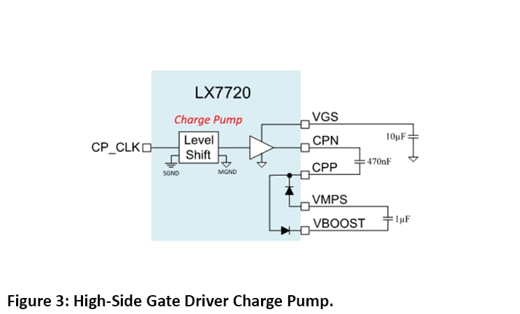
The LX7720 half-bridge motor driver stages have been introduced and you should now understand the charge pump approach used for the high-side NFET driver. The next article in this series will discuss the practical half-bridge driver stages using standard gate voltage and low gate voltage NFETs.
To find out more about the LX7720 and other radiation hardened mixed signal ICs.
Read other parts of this series:
Part 2: Practical half-bridge driver stages using both standard gate voltage and low gate voltage NFETs
Part 3: Introduction to the motor winding current sense amplifiers
Part 4: Topology choices applying current sense amplifiers within a half-bridge stage
Part 5: Separating a half-bridge into independent low-side and high-side drivers
Part 7: Connecting an LX7720 to a bipolar stepper motor
Part 8: Connecting an LX7720 to one or two unipolar stepper motors