
Custom Logic Peripherals for Improving Applications
Use custom logic peripherals on PIC® and AVR® MCUs to improve application performance.
The custom logic peripherals on PIC® and AVR® Microcontrollers (MCUs) are powerful tools that can be used to create small blocks of discrete logic that operate independently of the CPU. PIC microcontrollers have Configurable Logic Cells (CLC) while AVR microcontrollers have a Configurable Custom Logic (CCL) peripheral. For quick and easy setup, MPLAB® Code Configurator (MCC) can be used to setup and generate the APIs for the peripherals in use.
This article will focus on a few ways to use these peripherals to enhance designs.
How do the Peripherals Work?
Both the CLC and CCL peripherals are used to implement logic functions, but they take different approaches in doing so.
The CLC implements its logic function by selectively enabling internal logic elements into pre-defined configurations. The functionality of each input varies depending on the configuration of the cell. A few examples of the CLC configurations in the PIC18-Q40 family include:
- 4 Input AND
- OR-XOR
- 2 Input D flip-flop with reset
- 1 Input Transparent Latch with set and reset
The CCL peripheral on AVR MCUs works based on a Look Up Table (LUT). The input signals are used to look up the appropriate output of the peripheral, as shown in the (simplified) example below, which implements the logic function (A | (B & C)).
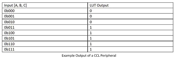
Additionally, latches and flip-flops can be connected to the output of the LUT(s) to implement synchronous logic functions.
Why Use Custom Logic Peripherals?
There are a couple of benefits to using the custom logic peripherals. Firstly, the peripherals can operate independently of the CPU once configured. If the CPU enters sleep mode, the peripherals can continue to operate. This assumes the input sources are still active in sleep, and RUNSTDBY is set for the CCL on the AVR MCUs.
Secondly, the peripheral can perform the logic operation faster than the CPU. The same operation performed by the microcontroller will take multiple clock cycles to complete. The minimum number of instruction clock cycles required is 2: solve the logic function, then change I/O pin state. In a practical application, it is almost certain to take more instruction clocks than this.
Use Cases
There are quite a few use cases for the custom logic peripherals. This is a brief list of some possible ways to use these peripherals in applications.
Implementing Logic Functions
Logic functions are the most straightforward application of the custom logic peripherals. Simple functions can be implemented using a single LUT or cell. More complex functions can be implemented by interconnecting the cells or LUTs together.
One use case for this functionality is to replace discrete logic ICs on the PCB, which reduces the Bill of Materials (BOM) and design area. Another design benefit of using the custom logic peripherals is flexibility. If during development the logic function needs to be changed, only a few minor software tweaks are required. Using discrete ICs would require swapping the IC and/or modifying the circuit to get the proper functionality.
Switch Debouncing
Another common use for the custom logic peripherals is in debouncing buttons or switches. There are quite a few ways to implement this – some methods are purely CLC or CCL based, while others use the custom logic peripherals in tandem with the on-board timers on the device.
AN2805: Robust Debouncing with Core-Independent Peripherals shows a few methods with CLCs, while section 4 of AN2451: Getting Started with Core Independent Peripherals on AVR shows a method using a CCL and the Event System (EVSYS) peripheral.
Increasing Signal Routing Flexibility
Most of the recent PIC and AVR microcontrollers released have either Peripheral Pin Select (PPS) (for PIC MCUs) or a PORTMUX peripheral (for AVR MCUs). These peripherals operate similarly, in that they both allow for flexible routing of digital peripheral signals on the microcontroller. The biggest difference between the two implementations is in the number of possible locations. The PPS peripheral has more options than the PORTMUX peripheral. However, even with PPS or PORTMUX, there can still be locations a specific peripheral may not be directly routed to.
By using a custom logic peripheral, it is possible to reroute some digital peripheral signals to/from a normally unavailable port/peripheral. The image below shows a simple pass-through configuration of a CLC that takes the PWM1_OUT1 signal and routes it through to the output of the CLC. PPS is used to set the output location of the CLC, bypassing the PORT unavailability for the PWM output.
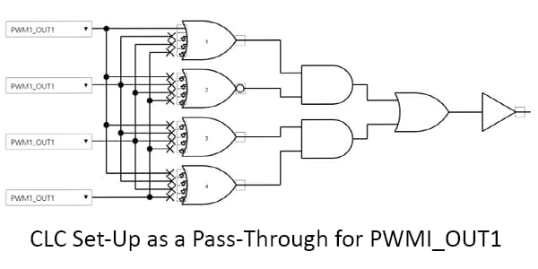
The CCL peripheral can be used similarly by setting the lookup table to be 1 when the input is 1 and 0 when the input is 0. Note, this requires the CCL’s clock to be running at least twice the frequency of the input signal. PORTMUX can be used to select the output location of the CCL.
A similar use for custom logic peripherals is for debugging internal signals. The custom logic can be used in pass-through mode to copy a peripheral output or digital signal to an I/O pin for direct observation and measurement. This is useful for debugging peripherals that do not have an output or for debugging a complex combination of core independent peripherals. As an example, if a program using a timer to automatically trigger the ADC was not working, then the timer signal could be output to an I/O to confirm the timer is running at the expected frequency.
Conclusion
Custom logic peripherals on PIC and AVR MCUs are simple, yet incredibly flexible tools. The CLC and CCL provide a fast and easy way to implement discrete logic both on and off the microcontroller. More information about these peripherals can be found at the link below and in the related technical documentation.