NVMe™ SSD Form Factors of the Future
NVMe SSD deployments are surging, fueling the need for new capacities, performance, power, connectivity and form factors. Here’s what you need to know about emerging form factors available for your new design.
NVMe NVM Express™ (NVMe) SSD deployments in enterprise and datacenter applications are surging, yet complications have emerged that prevent taking full advantage of these deployments. Applications in these markets demand varying needs of SSD capacity, performance, power, connectivity, form factor, thermal cooling, efficiency and TCO. Designing SSDs to meet these demands can be a challenging task – and one that needs careful selection of the SSD controller that would give the most bang for the buck. Let’s focus on the SSD form factor and what considerations need to be made during design.
Legacy NVMe SSD Form Factors
One of the most popular form factors, the 2.5-inch U.2 design, is used today for new enterprise SSDs as it leverages the server and storage systems built around hard disk drives (HDDs). The U.2 SSD supports single or dual port PCIe interfaces using a small form factor (SFF-8639) connector that is also compatible with standard SAS and SATA-based spinning disks and SSDs. However, 2.5-inch form factors, originally created for HDDs, are not always optimal for SSD thermal characteristics or target capacities.
Another highly popular SSD form factor is M.2. M.2 SSDs are found in laptops, boot drives, or applications where cost, size, power, and thermals are constrained. With the SSD ‘gumstick’ size, M.2 SSDs are ideal for low power applications where airflow is very limited. The advantage of the M.2 SSD is also its drawback, however, as M.2 SSDs cannot scale up in capacity, power, and performance due to their restrictive size and thermal characteristics.
Redefining NVMe SSD Form Factors
Due to the limitations of traditional NVMe SSD form factors, along with new evolving server form factor and connector requirements, arose initiatives to define new form factors for future SSD applications that include more storage performance and capacity, while continuing to provide a range of form factors for different server configurations. Some of the consideration include:
1. Common board dimension, connector, and pinout that can scale to support different PCIe configurations and thermal requirements
2. Scalability in operational efficiency, space, and capacity that are optimized for NAND flash memory
3. Total cost of ownership that results in lower operating and capital expenditures
4. Ability to support a dynamic range of solutions with storage agility and deliver high performance without compromise
5. Serviceability and manageability
NVMe SSD Form Factors for the Future
With the above considerations in mind, industry experts convened to adopt a new set of enterprise SSD form factors, the Enterprise and Data Center SSD Form Factor (EDSFF. ) Developed by 15 companies, the EDSFF worked to address the above concerns of data center solid state storage. The Storage Networking Industry Association now maintains the new form factor definitions as part of the SFF Technology Affiliate Technical Work Group (SFF TA TWG).
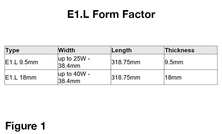
E1.L
The E1.L form factor was developed to maximize capacity per drive and per rack unit in a 1U server or storage array (JBOD, JBOF), with superior manageability, serviceability, and thermal characteristics. There are options for x4 or x8 lanes of PCIe while fitting vertically in a 1U chassis to allow for scalable bandwidth per drive, as well as heat sinks options for various power and thermal environments. It improves data center serviceability, and is designed to be hot pluggable and front access serviceable with LEDs built into an integrated enclosure.
It is also optimized for high-capacity and dense storage use cases. High capacity per rack unit can improve data center TCO by offering storage consolidation and more power efficient storage (TB/W).
Figure 1: E1.L Form Factor
E1.S
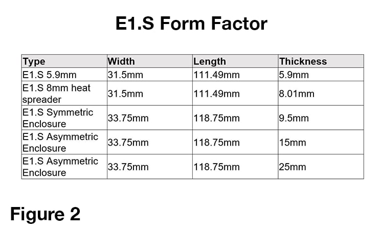
The E1.S form factor is a flexible, power efficient building block for hyperscale and enterprise compute nodes and storage. E1.S is a small form factor being just a bit longer than M.2 but wider to accommodate more media (NAND) packages for increase capacity per drive. It fits vertically in a 1U chassis, similar to E1.L. Different variants of E1.S offer improved flexibility for power, performance, scalability and thermal efficiency.
Figure 2: E1.S Form Factor
E3
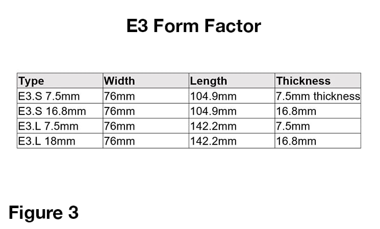
The E3 form factor has multiple options for length and height meant for 2U vertical orientation or 1U horizontal, but fits vertically and is optimized for mainstream 2U servers. Like the E1 family, they are hot pluggable / serviceable and higher capacity per drive vs U.2. The device maximizes space utilization in a 2U chassis by increasing the board real estate to allow for more media sites and packages, up to 50% increase vs U.2 single PCB designs. The long-term outlook is that E3 could be the true successor to U.2 in 2U servers. It will offer more power and performance vs. U.2 SSDs, better signal integrity at higher PCIe speeds (PCIe 5.0 and beyond), better cooling and reduced system infrastructure cost.
Figure 3: E3 Form Factor
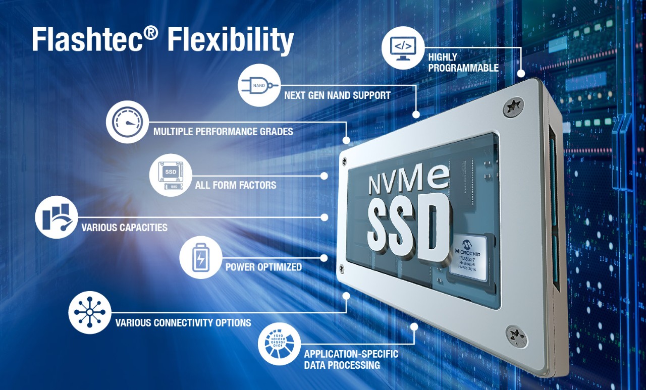
Flashtec® Family Enables Future SSD Form Factors
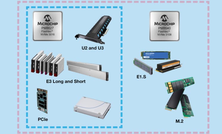
The Flashtec® NVMe 3108 PCIe® Gen 4 NVMe SSD controller was developed to support multiple form factors, including the space constrained legacy M.2 form factor and the newer EDSFF E1.S and E1.L form factors. It enables these, as well as, the larger PCIe add-in card, EDSFF E3, U.2 or even custom form factors for SSD suppliers building standard products or server OEMS, storage OEMs and hyperscalers that have decided to build their own custom drives and storage solutions. With its highly flexible and programmable architecture, the NVMe 3108 controllers are coupled with eight 1.2GT/s capable flash channels and combined with strong hardware accelerated RAID and exceptionally strong ECC provide future-proof support for next generation high layer count Triple Level Cell (TLC) and Quad Level Cell (QLC) NAND technologies.
The Flashtec NVMe 3108 boasts greater than one million IOs per second (IOPs) for random workloads and greater than 6 Gigabytes per second (GB/s) of sequential bandwidth. The solution provides end-to-end enterprise class data integrity with high reliability and critical security features including secure boot with Hardware Root of Trust, a mandatory requirement for much new data center infrastructure.
The Flashtec NVMe 3108 is nicely complimented by its big brother the NVMe 3016, a 16-flash channel controller that boasts greater than 2 million IOPs for random workloads and greater than 10 GB/s of sequential bandwidth.
Quick design of PCIe Gen 4 NVMe SSDs is enabled with Flashtec firmware development acceleration tools including an architectural simulator to enable development and debug of firmware, independent of silicon. Flashtec NVMe evaluation boards, as well as a complementary software development kit (SDK), are also available.
For more information about the Microchip Flashtec NVMe 3108 NVMe SSD controller and Flashtec NVMe 3016 NVMe SSD controller visit Flashtec® NVMe® Controllers.
Source: SNIA.org.
