Power Savings With VCI Logic Embedded Controllers
Since the advent of the mobile computing platform, OEMs have been optimizing their systems to meet the latest standards and offer the newest features in smaller and more efficient form factors. To meet these evolving requirements, we have been implementing efficiencies in the latest generations of our Embedded Controllers (ECs) to reduce their power consumption. These easy-to-use low-power features enable you to save power in your systems.
For example, many of our ECs offer VBAT-Powered Control Interface (VCI) logic, an interface exposed on the pins of these devices that allows a system to be powered in a very-low power state. This enables the EC to consume approximately 10 uA, which means it can be powered by a coin cell battery. The interface’s input and output signals (pins) allow the EC to be used to wake the system into full-on mode with minimal external hardware. In addition, this logic can be utilized to put the system back into its low-power sleep state (~10 uA) once all EC activity is completed.
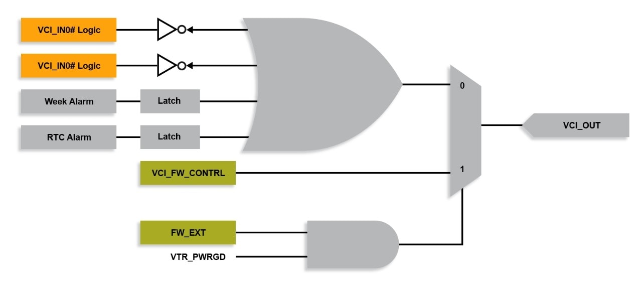
The following block diagram illustrates the VCI logic:

Note: VCI_IN0# Logic, VCI_IN1# and VCI_OUT are signals that are directly routed to the EC pin interface. Only two VCI_IN pins are shown in this diagram, however the number of supported VCI_INx# pins varies by product. All other blocks and signals shown represent internal logic of the EC that is powered by the coin cell battery.
The VCI_IN signals are the wake events for the system. Activating either low will cause the VCI_OUT signal to go active high. VCI_OUT should be connected to the system power source. When VCI_OUT is high, it will turn on power to the rest of the platform. VCI_IN signals can be used for a platform’s power button, a Wake-on-LAN (WOL) event or any other signal when the system is required to come out of this deep sleep state.
If the VCI_FW_CONTROL signal is activated, the system will return to the low-power state when the system has finished servicing the wake events. This internal signal is asserted by the firmware when the system needs to re-enter this sleep state.
In addition to being able to wake from an external source, the VCI logic can enable the system to wake up via the EC’s internal WEEK Alarm and Real Time Clock (RTC) Alarm signals. When the system is put into very-low-power or hibernation states, the Week Alarm or the RTC Alarm can be easily programmed to wake the system periodically for maintenance or other purposes. In many cases, a system is required to wake up periodically to perform checks and monitor status to ensure all is well, and it will return to the deep sleep state again if no system issues are detected.
So, if you need an easy way to manage your system’s power usage as it goes from the deepest sleep state to fully on and then back to the deepest sleep state, the VCI logic available in our latest ECs may be an excellent option for your application. To take advantage of this key feature for power savings, consider using an MEC1418 or MEC1701 in your next computing application.