Is It Time to Migrate to the eSPI Bus?
Most computer users are aware of the existence of high-speed buses because of the PCI Express® (PCIe®) add-in cards or the walk-up USB connectors available in their PCs. However, they may not know that a low-speed bus can be also found on all computers. For many years, this bus has been used to connect various devices, such as an Embedded Controller (EC), Baseboard Management Controller (BMC), Super I/O (SIO) controller, system Flash storage that is used to store the BIOS code, and the Trusted Platform Module (TPM) to the system core logic. This low-speed bus was originally called the Low Pin Count (LPC) bus.
As the needs of the computing industry continue to evolve, the more flexible and efficient Enhanced Serial Peripheral Interface (eSPI) bus was introduced to overcome the limitations of the LPC bus. Supported by the latest PC computing chipsets, this all-in-one bus was designed to replace the LPC bus as well as the SPI bus, SMbus and sideband signals. For designers of computing applications, migrating from the LPC bus to the eSPI bus offers these benefits:
- Cost savings: Because the LPC bus requires a considerable number of sideband signals for power sequencing and sleep mode support, it uses 13 pins to connect to the system processor. The eSPI protocol uses virtual wires to implement some of these signals, so only five or six pins are required in most implementations, which reduces the pin count and cost.
- Lower voltage: The LPC bus requires 3.3V I/O signaling, while the eSPI bus uses 1.8V to significantly reduce system power consumption.
- Simplified board layout and design: The LPC bus requires a synchronous 24 MHz or 33 MHz clock, which requires careful board layout to match the clock and data signal lengths to all devices. The eSPI bus uses a master-driven clock from the system processor, which simplifies the board layout and design.
- Low-power states: While the LPC bus can only run when the system is in the S0 state, the eSPI bus can run when the system is in a low-power S5 state. This allows many system improvements, including:
- Sideband signals used to support power sequencing can be implemented as virtual wires.
- The EC can share the system SPI storage during boot time, eliminating the need for additional SPI chips in the system and reducing system cost.
- The eSPI bus can be used for communication between the core logic and the EC in S5 states. This allows additional sideband communication buses, such as I2C and PECI, to be removed, which reduces additional signals from the board.
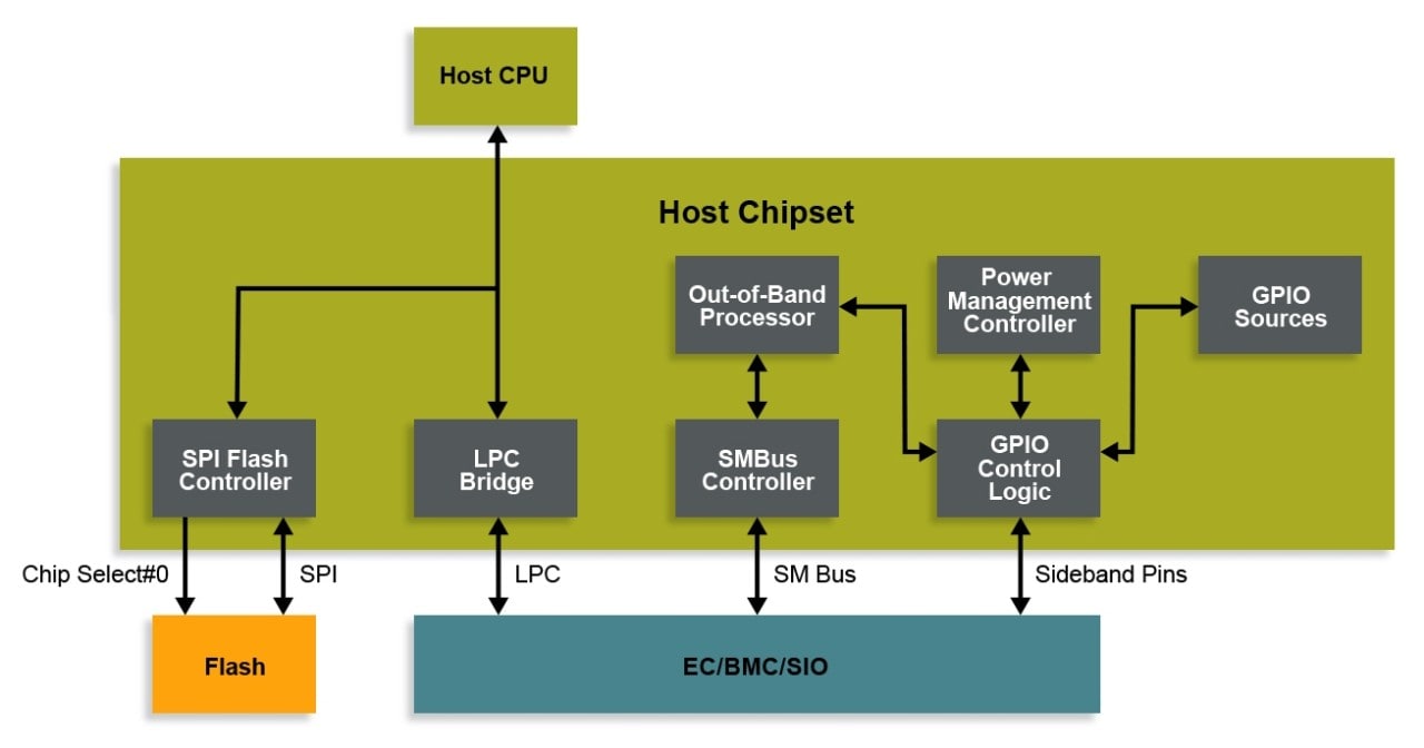
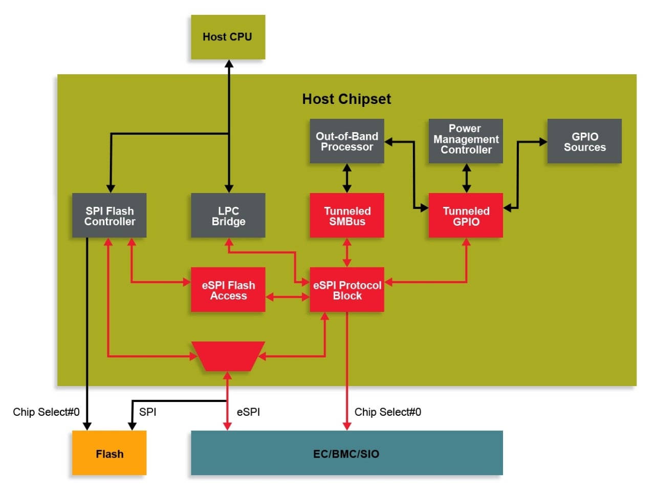
The following two diagrams show the differences between an LPC based-system and an eSPI-based system.

Figure - LPC System Diagram

Figure - eSPI System Diagram
The eSPI specification specifies several modes or channels that enable communication over the bus:
- The Peripheral channel is used to communicate with devices located in the EC, BMC and SIO that were formerly found on the LPC bus. They include UARTS, mailbox registers, port 80 registers, embedded memory interfaces and the keyboard controller. The Peripheral channel also includes support for a Bus Mastering channel. The Bus Master capability allows the EC to read/write data directly to/from the main system memory.
- The Virtual Wire Channel is used to transmit the sideband signal information to/from the EC, BMC and SIO. Interrupts from peripheral devices, such as a UART, are also transmitted over the Virtual Wire channel. This channel greatly reduces the pin count and cost of the eSPI bus as compared to the LPC bus.
- The Out-Of-Band (OOB) Message Channel is used to tunnel SMBus traffic over eSPI. These messages can include system logic and processor temperature values or SMBus Management Component Transport Protocol (MCTP) packets.
- The Flash Access Channel allows the system processor to share the system SPI Flash between the BIOS, Management Engine (ME) and the EC, BMC and SIO. This reduces system cost by reducing the number of SPI Flash chips in the system.
If you are ready to migrate your design to support the eSPI bus, our MEC14xx and MEC17xx embedded controllers are excellent options. Microchip was one of the first companies to support the eSPI bus and was selected by Intel® to be their validation partner for the eSPI development. This means our devices have been fully validated with the Intel eSPI master. Intel has also selected our ECs for their reference validation platforms, which ensures that they are fully supported by Intel. Visit our Embedded Controller Design Center to learn more about how to transition your computing design to this new bus technology.