Accurately Measuring Current With Microcontrollers
When measuring current, there is an increased opportunity for measurement error. Learn more about these sources of error and how to reduce and eliminate them.
Introduction to On-Chip Analog CIPs to Reduce or Eliminate Errors
Some applications, such as power electronics, safety systems and gas monitors, may require the measurement of currents flowing in a circuit. While measuring voltage with an Analog-to-Digital Converter (ADC) is a straightforward process, measuring current is not. The added complexity of current measurements increases the number of opportunities for measurement error. This blog post will discuss some of these sources of error and how to use the on-chip analog Core Independent Peripherals (CIPs) to reduce or eliminate these errors.
Scope of the Problem
Measurement errors are more likely to occur when high currents are flowing. But these errors are not exclusive to just power systems. Poor grounding and signal management can affect small signal measurements as well. If the sum of all errors and inaccuracies exceeds ½ of a Least Significant Bit (LSB), or in other words, the resolution per bit of the ADC, then the error will affect the measurement. Understanding the sources of potential error maximizes the capabilities of current measurements.
Showing the Problem
Let’s start with a simplified view of a low-side current measurement circuit. As current flows through the load, it passes through a sense resistor, generating a voltage across the resistor from Ohm’s law (V = IR). In an ideal world, measuring this circuit is as simple as connecting an ADC input to this current shunt.
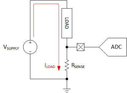
Simplified Current Measurement Circuit
Now, let’s look at this diagram again, but with some common parasitic elements added in. The current sense resistor is no longer the only source of resistance on the low-side of this circuit. The resistance of the ground return (RGND) is in series with the sense resistor. This resistance typically comes from the wiring, the solder connection and the copper of the Printed Circuit Board (PCB).
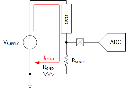
Current Measurement Circuit with Parasitic Resistance Shown
If the shunt resistor is relatively large compared to RGND then the effect is negligible. But, if the ground return resistance is even a few percent of the shunt resistance, this will add a significant amount of error. For instance, if a 1 ohm, ±1% shunt resistor is used, a mere 10 milliohms of resistance would be equivalent to the tolerance on the resistor, turning it into a 1 ohm, -0%, +2% resistor. The effect becomes more noticeable as the resistance of the current shunt becomes smaller. To reduce the effect, there are a few methods to compensate and correct for this error.
Reducing Measurement Error
Increasing Shunt Resistance
First, let’s look at increasing the resistance of the shunt. In power applications, this isn’t an optimal solution. As the resistance increases, the power dissipated (P = I2R) by the resistor also increases, which reduces efficiency. To maintain the same amount of current through the load, the required compliance (voltage) from the supply must increase.
This approach will only be possible in certain applications and circumstances.
Reducing Parasitic Resistance
The opposite approach is to decrease the parasitic losses. To minimize losses, the current return path should be as short as possible with as low of an impedance as possible. Free calculators and tools online can estimate the amount of resistance for a specific trace width on a PCB.
Measuring Differentially
Some microcontrollers (MCUs), such as the PIC18F56Q71 family, PIC16F17146 family, AVR® DD family or the ATtiny1627 family, contain differential ADCs that can measure the voltage difference between two inputs, rather than in reference to the MCU's ground.
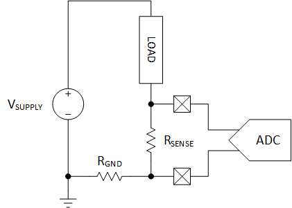
Differential Measurement of a Signal
This removes the offset without any changes to the circuit, although the other methods for minimizing parasitic resistance and calibration (see below) are still valid and worth adding if possible. This method can also be used on high-side sensing, so long as the (absolute) input voltages remain within the MCU’s absolute maximum rating.
Measuring Pseudo-Differentially
If the MCU lacks a true differential ADC, it is still possible to perform a differential measurement with a single-ended ADC by performing a pseudo-differential measurement. In this measurement mode, the ADC first measures the high side of the current sense, then the low side. By subtracting the results from each other, a differential result can be determined.
However, this assumes DC (steady state) behavior of the signal. A better version of this measurement performs three measurements in the pattern high side, low side, then high side. The two high-side measurements are averaged before subtraction to correct for changes in the signal between the samples.
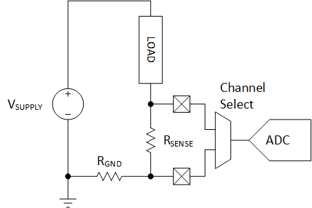
Measuring Pseudo-Differentially
Calibrating Out Errors
Outside of the analog domain, another approach to reducing error is to perform system calibration. This can be performed in the factory, or in the end product. To perform calibration, apply known circuit conditions to the measurement circuit, acquire a measurement from the MCU and then compute the error from the expected. The measurement error correction(s) can be stored in device memory for future use, although drift may occur over time. Then, at runtime, the MCU applies the error correction(s) to the results before processing.
Signal Scaling Issues
From what we have discussed so far, the voltage across the current sense resistor has been assumed to be a fairly large signal within the measurement range of the ADC. But this is not commonly the case. As mentioned earlier, the current sense resistor dissipates I2R power. Lowering the resistance of the current shunt reduces dissipates the amount of heat and improves power efficiency.
Using a Programmable Gain Amplifier (PGA)
Some differential ADCs (like those of the ATtiny1627 family) have a built-in Programmable Gain Amplifier (PGA) that amplifies differential signals. This feature is useful when the signal is so small only a fraction of the ADC’s measurement range is used. By amplifying the signal, even very small differential signals can be directly measured by the microcontroller.
A More General Approach
MCUs that don’t have a PGA will have to take a different approach. One option is to minimize parasitic resistance and utilize an on-chip Operational Amplifier (OPAMP) CIP. The OPAMP can be used to amplify the output of the current shunt to a larger, more measurable value. Additionally, some devices contain an internal resistor ladder that can be used for OPAMP gain without external components. For tighter gain control, external resistors can be used with the OPAMP if desired.
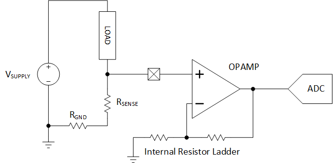
Current Sense Amplifier
A limitation of this approach is that differential amplification with two OPAMP CIPs would be very difficult to implement in a useful fashion. For this approach to work, both OPAMPs would need to have identical gains, likely from precision-matched resistors, and matched offset voltages which would be difficult to correct to. If mismatched, some amount of error either as a gain error or as an offset error, would be generated. In this case, a discrete instrumentation amplifier would be a better choice, as they contain matched resistors.
Conclusion
This blog post has discussed some of the complexities of measuring current with an MCU. More information about the PIC18F56Q71 family and ATtiny1627 family is available on our site.