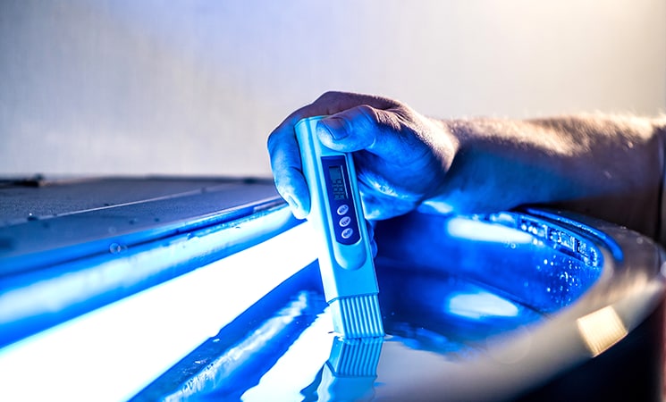
Total Dissolved Solids (TDS) Meter Using Relaxation Oscillator
In this post, we will discuss why you should care about TDS and how we can implement a TDS measurement tool using 8-bit microcontrollers (MCUs).
What is TDS?
Before discussing how you can use our 8-bit MCUs to measure Total Dissolved Solids (TDS), let's briefly explain what a TDS is. TDS is a key factor that determines the quality of a given water source and can be understood as the presence of inorganic or indissoluble salts and small amounts of organic matter in water. Higher levels of impurities make the solution more conductive, which can be quantified by using a conductivity probe that measures the number of ions in solution. For example, by adding salt to water, water molecules separate the sodium and chlorine ions, which increases conductivity of the solution. This allows electrical currents to be easily carried in solution by these ions.
So, why should you care about TDS? TDS can quantify the quality of water by measuring the amount of certain impurities present. Water that has an excess amount of these substances dissolved into it is toxic to humans and the environment. A high level of TDS can interfere with the effectiveness of sewage treatment, cause unwanted buildup in city pipes, cause unsafe fertilization of crops and ultimately affect standard drinking water.
Implementing a TDS Measurement Tool
Now that we have covered what TDS are and how they can affect our daily lives, let’s talk about how we can implement a TDS measurement tool using 8-bit MCUs. One of the ways to measure TDS is by using a voltage divider, as shown in Figure 1. In this circuit, the contaminated water acts as a variable resistor, and the voltage across the variable resistor can be measured using an Analog-to-Digital Converter (ADC). From these values, TDS can be calculated. With a voltage divider, TDS values can be measured over a wide range with minimal required circuitry. One of the disadvantages of TDS is that the accuracy of the system decreases over time as corrosion will build up on the probe pins through a process called electrolysis, which results in the probes needing to be cleaned and/or recalibrated regularly. Additionally, electrolysis can cause the split of H2O resulting in small amounts of hydrogen and oxygen gas being formed, which could be hazardous.

Figure 1: Voltage-Divider Circuit
Another method that can be used to measure TDS values is to use an operational amplifier (op amp) as a relaxation oscillator, as shown in Figure 2. In order to understand how this method measures TDS values, let’s briefly discuss what a relaxation oscillator is. The circuitry used to create this consists of a capacitor, multiple resistors and an op-amp. Initially, the op amp's inputs are imbalanced. To correct the imbalance, the op amp pushes or pulls the output in one direction. As this occurs, the output shifts and the op-amp must start moving in the opposite direction to try and counter this change. The output begins to oscillate in this state. This ultimately generates pulses on the output of the op amp.
The relaxation oscillator improves the long-term stability of the TDS meter by significantly reducing the rate of corrosion built-up on the probe, because the probe modulates between zero and positive, reducing the attraction of the ions to the probe.
The TDS probe is connected as an input to the op amp and acts as a variable resistance (R1 in Figure 2). The input value of the capacitor (C1 in Figure 2) determines how quickly the oscillator oscillates. By varying this capacitor value, the frequency range can be modified.
The pulses generated by the op amp can then be captured by the Capture/Compare/PWM (CCP) peripheral. The CCP captures the op amp output, which can then be used to calculate the pulse time period and be translated into the TDS values.

Figure 2: Relaxation Oscillator Circuit
Both the voltage-divider circuit and the relaxation oscillator circuit provide solutions to measure TDS values using our 8-bit MCUs. If you’re interested in learning how to implement the TDS measurement using the relaxation oscillator circuit, be sure to check out the project on TDS measurement using a PIC16F17146 MCU.