Rotary Encoder Applications using Microchip Field-Programmable Gate Arrays (FPGAs) and System-on-Chips (SoCs)
Learn more about Microchip's devices optimized for rotary encoder applications with special requirements and safety relevance.
Rotary Encoder Working Principle
Rotary encoders are used to precisely measure the angular position of an electric motor for accurate control. These encoders are typically mounted on the shaft of the electric motor:

Being mounted on the motor shaft brings significant system constraints:
- Doughnut-shaped printed circuit board (PCB) with mounting hole in the middle → space constraint
- Thermal conductivity from the motor → high operational temperature for the electronics
- High temperature for electronic → reliability and lifetime of electronics reduced
These constraints boil down to the requirement of reliable components with little self-heating and a small physical footprint. As those encoders are typically manufactured in very high volume, the system-cost of cooling and PCB manufacturing are important design factors. An additional design factor often involved in these systems is functional safety to reliably know if measurement values are valid or if the system needs to be brought into a safe state, i.e., stopped.
Typical diameters of these doughnut-shaped PCBs go down to 35 mm, which limits the physical size of selected components to approximately 10 × 10mm² or less. The encoder boards are directly affected by the heat developed by the motor and under working conditions can reach a temperature of 95°C and, for a certain period of the lifetime, even 105°C. At these temperatures, the self-heating of electronics due to leakage currents is already strongly present—some semiconductors may even suffer thermal runaway.
SmartFusion2 SoC in the FCSG158 Package
Microchip has designed a specific device for these applications: the SmartFusion2 SoC in the FCSG158 package. This device features an Arm M3 Microcontroller with an attached FPGA fabric of approximately 25.000 Logic Elements and an optimized device-package of 9 × 9mm². This device is highly optimized for these harsh operating conditions and design constraints.

The routing-optimized package allows a full breakout of the package with only two signal-layers on the PCB, keeping the PCB simple and low. The free space in the ball-grid of the package allows the placement of cost-efficient 0.3 mm vias for the inner ring and the placement of decoupling capacitors directly under the package close to the supply pins in the middle of the package:

This SmartFusion2 device provides 82 I/Os, 70 of which are capable of interfacing to 3.3V and 12 can natively interface to 2.5V or via resistive dividers to 3.3V. Additionally, for situations requiring high-speed communication, one transceiver pair is available that can run up to 5 Gbps and support PCIe Gen2. An on-chip Arm M3 Microcontroller can also be utilized for typical housekeeping and communication purposes.
Due to the power-optimized architecture of the SmartFusion2 and its resulting small self-heating, the device can be operated with ambient temperatures close to the maximally specified temperature range (100°C/125°C). To get accurate estimations for the power consumption and the self-heating of the device, it is recommended to use the Microchip Power Estimator for SmartFusion2 SoCs and Igloo2 FPGAs or for PolarFire FPGAs and SoCs.
As mentioned above, encoder-data is often safety-critical with the requirement for the FPGA design to also become safety-certified or be of mixed criticality levels. Such a safety certification is supported by Microchip with the SmartFusion2/Igloo2 safety package. The SmartFusion2 and Igloo2 devices are certified for Functional Safety according to IEC 61508 based on proven in use. The appropriate safety package contains the safety certified development environment Libero SoC 18.3 SP4, 28 IP-cores very often required in FPGA designs, the safety manual for these devices and utilities to calculate the probability of hardware failures.
As Microchip FPGAs and SoCs are immune to single event upsets (SEUs) on the configuration memory, the permanent hardware failures are the only contributor to the FIT-calculation required for the safety discussion. FIT stands for failure in time and 1 FIT is equal to one failure in 109 hours. For typical SRAM-based FPGAs, the soft FIT caused by SEUs is dependent on the exact architecture and the complexity of the chosen device and is typically in the range of about 400 FIT. This considers that safety-relevant functionality is usually only occupying a fraction of the FPGA-fabric. On top of this soft FIT, the permanent failures are added.
The FIT rate for permanent failures is derived from vendor measurement data at increased device stress levels to accelerate aging effects that mainly contribute to device failures. These measurement results are the base to calculate hardware failure rates under the desired operational conditions based on the Arrhenius relationship
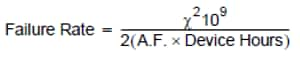
where A.F = acceleration factor.
The visualized result of that calculation is:

When doing the calculation for a complete FPGA, the resulting FIT rate at ambient temperatures of >90°C, which rotary encoders often have as operating conditions, can reach failure-rates of around 100 FIT. For functionally safe designs, this is significantly too much.
In other words, one either needs to keep the device temperature low or, for safety calculations, keep the size of the relevant functionality small.
The Microchip safety package contains the appropriate data and utilities to determine the FIT rate of the safety-relevant fraction of the overall design and thus easing getting a design certified.
In addition, Microchip collaborates with industry experts that can provide consultancy services for functional safety designs. For FPGAs specifically, this is Expleo, who is available in 30 different countries worldwide.
In summary, Microchip provides a complete package of devices optimized for rotary encoder applications together with the safety package and consultancy experts. Get in contact with your appropriate Microchip representative to learn more.