Power Switches: Part One
This is the first article in a two-part discussion introducing our family of radiation-hardened power switches. After reading this, we hope you walk away with an understanding of what power switches are and why and where they are used.

Understand the Power Switches
This first blog post provides an overview of the common types of power switches with some interesting history and then uses the two simplest products as examples to show the architectures of redundant power switching. The second blog post will introduce more complex parts that add features to manage more complex failure scenarios.
What Are Power Switches and Where Are They Used?
There are three basic types of power switches. This first one is called a low-side switch because the switch connects the load to ground.
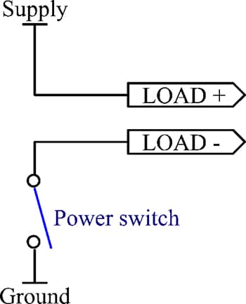
Figure 1. Low-Side Power Switch
Alternatively, the switch can be placed in the supply rail, which is known as a high-side switch.
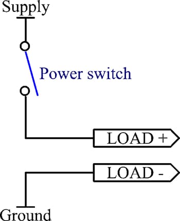
Figure 2. High-Side Power Switch
Finally, there is a mechanical relay approach with an isolatable power switch. Relays are useful to control a load that needs to be galvanically isolated because the load doesn't share a common ground potential with the controller. They are common to switch high currents and voltages. Relays are also robust in the event of short-term current and voltage spikes.

Figure 3. Isolatable Power Switch
Integrated low-side power switches have been offered since the 1970s for applications such as dot matrix pin drivers and relay/solenoid drivers. The MIC5801 shown here in Figure 1 includes latches and integrates eight drive outputs. The latches allow multiple MIC5801s to be multiplexed on the same eight input lines, with each MIC5801 individually strobed when its outputs need updating.
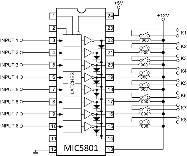
Figure 4. MIC5801 Latchable Low-Side Driver
The MIC5801's output stage is shown in Figure 5. It's a Darlington Negative-Positive-Negative (NPN) stage, with diode protection against voltage transients below ground or above the load supply. It's easy enough to duplicate with discrete components, but using an Integrated Circuit (IC) saves space and cost.
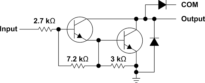
Figure 5. Low-Side Driver Output Stage
Satellites are usually power constrained, operating from a mix of solar and battery power. Because of this, unused systems are powered down when not in use. Power switches are normally high side because inputs and outputs are ground referred and it is simpler not to break the ground. Also, space systems usually require redundancy and a system such as the one shown in Figure 6 may have to allow the 3.3V supply to be switched from a dead one to a working one. Also, the module itself may need to be electrically disconnected on failure to avoid drawing unnecessary power.

Figure 6. High-Side Power Switching to Modules
The AAHS298B is an octal high-side power switch for space and is radiation hardened by design. This means that from the initial stages of design we use special processes, devices and design techniques that are proven to give radiation tolerance. The AAHS298B contains eight independent 700 mA power switches operating from a common supply in the range 10V to 75V (Figure 7).

Figure 7. AAHS298B
Here's a comparison of a commercial high side driver, our MIC2981, with the AAHS298B. Like the MIC5801 low-side driver discussed earlier, these are simple parts. The AAHS298B is packaged in a hermetic ceramic Small Outline (SO) package that is required for most space applications. It still offers the same 1.27-mm lead pitch as the commercial plastic SO package.
The AAHS298B includes more protection around the input and output and has thermal shutdown, but there's no over-current protection. Instead, the AAHS298B is designed to fuse (as in open) an output's bond wire to fail-safe open if overloaded long enough. This could occur during a catastrophic event such as a short circuit fault.
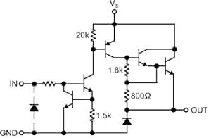
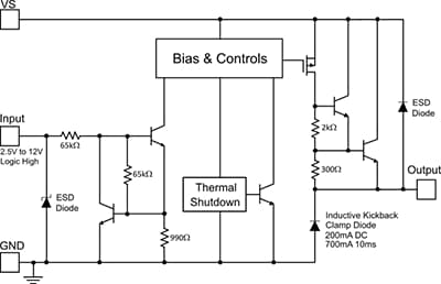
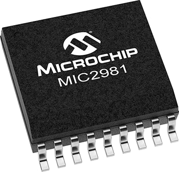
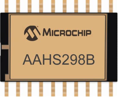
Figure 8. MIC2981 High-Side Driver Compared to the AAHS298B
A catastrophic event might be short term or be self healing and needs to be powered up again. Alternatively, there might be a failure in the AAHS298B output itself. Either way, there's a need for redundancy in the power switching, meaning a backup way of powering the load in case of fault.
The classic way to provide redundant power switching is to use redundant power switches, meaning two instead of one, and combine their outputs through diodes (Figure 9).

Figure 9. Redundant Power Switching Through Diodes
The diodes prevent the power bus back-driving through a damaged driver. Say, for example, the top driver is damaged, perhaps with its output shorted to ground. The path through the bottom driver, a redundant path, to the power bus output is fine. The top diode is reverse biased and prevents the damaged top driver from pulling down the power bus (Figure 10).

Figure 10. Driver Fault Blocking
There is another fault to consider and that is a diode failure leading to an open or short. This is the purpose of our LX7710 radiation-hardened-by-design eight pair diode array. The LX7710 is offered in the same hermetic package as the AAHS298B. All diodes are rated at 700 mA, matching an AAHS298B output. The diodes are in series pairs, and as shown in Figure 11 are normally used as two pairs in parallel.
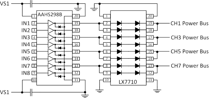
Figure 11. AAHS298B Used With an LX7710
Each set of four diodes replaces just one diode in Figure 9 and Figure 10. Four diodes are needed for redundancy. Consider a single driver as shown in Figure 12. In normal operation, current flows through both pairs of diodes.

Figure 12. Redundant Diodes—Normal Current Flow
If one diode fails to open, there is still a good path through the remaining dual diode (Figure 13).

Figure 13. Redundant Diodes—Current Flow With One Open Diode
And if a diode is shorted, the current will still pass through that pair, with some current going through the top pair too depending on the voltage drops across each path.

Figure 14. Redundant Diodes—Current Flow With One Shorted Diode
Figure 15 shows a redundant setup which includes the power driver, so two AAHS298Bs driving the same eight loads through diodes. To turn on the CH1 output, for example, take either SEL_CH1_VS1 or SEL_CH1_VS2 high, or take both high. The diode ORing prevents back-driving from one channel to the other. The diode arrays use two in series so that if one diode fails short, the remaining diode still works as a blocking device. This architecture therefore protects against a single point of failure since the relay will be driven if one diode or one driver fails.
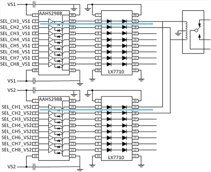
Figure 15. Complete Redundant Driver
That concludes the first blog post covering simple power switching. Hopefully you now understand what power switches are, why and where they are used and are familiar with the architectures of redundant power switching. The second blog post will introduce the LX7712 and LX7714 power switches, which include features such as automatic fault handling with timers, current limiting, current telemetry and slew rate control.