PIR Motion Sensing with the ATtiny1627 MCU Family
Sense motion and environmental changes with a passive infrared sensor (PIR) from the ATtiny1627 MCU family.

In the world of tech, motion sensing devices have become increasingly popular. That is where the Passive Infrared (PIR) motion sensing comes into play. PIR sensors are a type of sensor that passively absorbs infra-red (IR) radiation in the field of view. When the amount of IR in the environment shifts, the sensor’s output changes. This appears as a small AC signal on a large DC common-mode voltage. By monitoring the differential voltage, which cancels out the DC offset, changes in the environment, such as a person entering or exiting, can be detected.

The ATtiny1627 family of microcontrollers contains a differential Analog-to-Digital Converter (ADC) with a Programmable Gain Amplifier (PGA), which can provide the sensitive analog interface for this sensor. The ADC in the ATtiny1627 family can reach a maximum resolution of 17-bits via oversampling, however it is normally used at 12-bit resolutions.
Analog Sensor Conditioning and Interfacing
Standard single-ended ADCs cannot reliably measure a PIR sensor directly. The AC signal (when present) is extremely small, and the DC common-mode voltage is very large. The PIR sensor output can be treated as a differential signal, rather than as a signal measured with respect to ground.
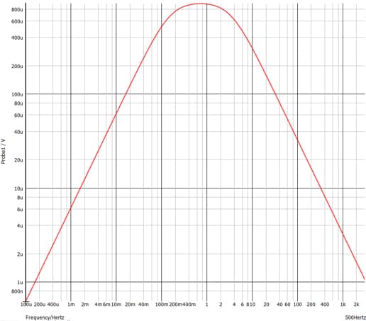
Before the signal enters the ATtiny1627 for differential amplification and measurement, two RC low-pass filters (at differing roll-off frequencies) are used to create the “positive” and “negative” components of the differential signal.

The positive-side RC filter is built from a 470kΩ ohm resistor and a 100nF capacitor for a cutoff frequency of 3.38Hz. This filter lets the AC signal from the PIR sensor and the DC bias through while blocking high-frequency noise.
The negative-side RC filter is built from a 470kΩ resistor and a 2.2µF capacitor for a cutoff frequency of 0.154Hz. This filter is designed to pass the DC bias while rejecting the AC signal from the PIR sensor.
The two low-pass filters create an effective bandpass filter–frequencies lower than the cutoff frequency of both filters appear on both inputs (minus any losses from the filters). Since the ADC is differential, these signals are subtracted out. Signals that are higher than both cutoff frequencies are heavily attenuated by the RC filters, which minimizes their impact. Finally, signals that are attenuated by one filter and passed by the other will be the strongest input signal. The image below shows a simulation of the filter response in MPLAB® Mindi™ Analog Simulator.
Software Operation
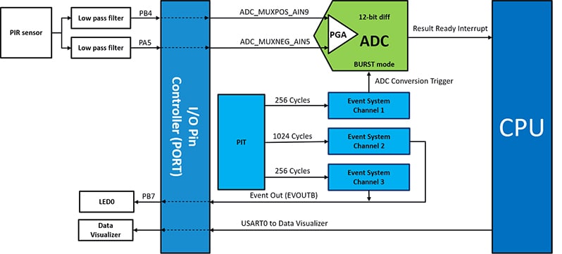
On startup, the ATtiny1627 initializes the peripherals in use:
- Differential ADC with PGA
- Periodic Interrupt Timer (PIT)
- Event System (EVSYS)
- Universal Synchronous and Asynchronous Receiver and Transmitter (USART) (for serial communications, if enabled)
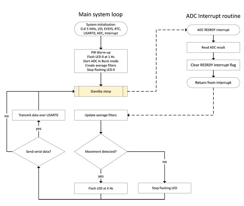
Then the microcontroller enters a warmup phase where it initializes 2 digital filters on the device – a short-term averaging filter and a long-term averaging filter. These filters are used to detect motion over time. During warmup, the LED flashes at 1Hz.
After initializing the peripherals and digital filters, the microcontroller enters sleep. In sleep, the power consumption of the microcontroller is very low, which extends battery life (for more information about power consumption with various settings, please consult the Application Note). The ADC is periodically triggered without waking the microcontroller through the PIT signal connected in the Event System.
After performing the conversion(s), the ADC wakes up the microcontroller by triggering an interrupt. The microcontroller updates the digital filters with the value from the ADC. To determine if motion has occurred, the microcontroller compares the difference between the long-term and short-term filters to see if it passes a threshold. If the threshold is exceeded, then motion is detected, and the LED I/O line is connected to a 4 Hz signal from the PIT.
The ATtiny1627 family of AVR® MCUs are equipped with a fast differential ADC and hardware-based Core Independent Peripherals for low-power operation in real-time control and sensor node applications. To get started developing with this family, the ATtiny1627 Curiosity Nano Evaluation Kit (DM080104) is available. This compact evaluation kit is perfect for rapidly prototyping your sensor node, real-time control or other application.
The board integrates seamlessly with MPLAB® X, Microchip Studio and IAR Embedded Workbench Integrated Development Environments (IDEs) to best suit the way you work. Attach it to a breadboard or combine it with the Curiosity Nano Base for Click boards™ (AC164162) to add mikroBUS™ sockets to easily incorporate sensors, actuators or communications interfaces into your design. This is just one example of the flexibility of the products in the ATtiny1627 family of AVR MCUs.
Conclusion
This application demonstrates one of the benefits of using the differential ADC in the ATtiny1627 family of MCUs. For more information on this application, please see the application notes linked below.
Read more about this application: Low-Power, Cost-Efficient PIR Motion Detection Using the tinyAVR® 2 Family (microchip.com)
Visit the ATtiny1627 Homepage: ATtiny1627 | Microchip Technology