How to Write Bare-metal Code for PIC® or AVR® MCUs
Learn how to write bare metal C code quickly and understand the drivers generated by MPLAB® Code Configurator (MCC).
This article describes the symmetrical application notes PIC1000 and AVR1000b, showing how they apply to the code generated by the phenomenal MPLAB® Code Configurator (MCC). This article walks through how to use these application notes to look under the hood of MCC as a reference to the bare metal code that is generated. Or if you start with the bare metal application notes, to learn how to write bare-metal code from scratch, this article will show you how to apply this knowledge to design with MCC more confidently and flexibly. It is your choice! The application notes describe in detail the reasons for the naming conventions and register access methods for each architecture, to help you make sense of the differences between low-level PIC® and AVR® MCU code. No matter how you approach your designs, you will be able to write bare metal C code quickly and understand the drivers generated by MCC.
Selecting an MCU for Your Application (Based on Differentiated Peripherals, Not Experience on a Particular MCU Family)
Combining the individually impressive PIC and AVR microcontroller (MCU) families, Microchip has a market-leading range of 8-bit MCUs. As an embedded engineer, ideally selection of an MCU for a given project is based on which device (peripheral) best enables the challenging-to-implement features of your application. Quite often, this is determined by the combination of differentiated peripherals on that MCU. For example, you may have tough analog measuring application requirements, demanding a careful examination of the MCU’s analog to digital converter (ADC). In one application the PIC MCU’s 10-bit Analog-to-Digital Converter with Computation (ADCC) peripheral (video) may have an advantage, due to the various types of core independent post-sampling computation supported. For another application, the AVR MCU’s 12-bit differential ADC, may have advantages due to its resolution or operation with the AVR MCU’s Event System. Both ADCs offer relatively specialized functionality, offering certain advantages, depending on the application requirements.
Often the support of a familiar ecosystem is a significant impact on MCU selection. To keep the focus on choosing the optimal MCU and peripherals for their design, over the last couple years great efforts have been made to align the tools support for the PIC and AVR MCU product families. Microchip remains committed to supporting new AVR devices in the Atmel Studio 7 and Atmel START ecosystem. In addition to this, AVR MCUs have been added to both MPLAB X Integrated Development Environment (IDE) and MPLAB Code Configurator (MCC), unifying the development experience between these MCU families. The support of a common tool’s ecosystem is designed to get you going very quickly with new MCU families, significantly lowering the barrier to exploration. However, for an embedded developer, comfortable development with an MCU goes deeper than the tools ecosystem, all the way down to register-level, or bare-metal, coding.
Understanding All of the Code in Your Project
Code generation tools such as the MPLAB Code Configurator (MCC) or Atmel START are a fantastic way to save a lot of time in your design. However, you may never feel completely comfortable with these tools if you do not understand the code that they generate. Ironically, you may only trust the tool when you no longer need it. As an embedded developer, you also know that you are unlikely to enter production without having to at least modify some register-level code yourself.
Bare-metal Coding: Using a Device Datasheet and Header File as Primary Programming References
MCUs are composed of several building blocks or modules: CPU, SRAM, Flash, EEPROM and peripherals (e.g. an ADC). Each of these are defined in the device datasheet and are configurable through registers. The reference to ‘metal’ in ‘bare-metal coding’ refers to the device registers, so it refers to the practice of writing the register-level code required to configure an MCU’s modules. The form of this register-level code is influenced by the device header file, which is in turn influenced by the structure of the MCU’s peripheral modules (datasheet). So, writing bare-metal code efficiently requires a working knowledge of the datasheet module structure as well as header-file definitions. Besides code examples, the primary programming references for developing at this level are therefore typically the MCU datasheet and device header file.
Bare-metal coding is an embedded development skill, which tends to be mastered over the course of several projects on the same MCU family. For a specific MCU the engineer becomes familiar with the implicit patterns of how the datasheet modules and header files for an MCU family are organized. Knowledge of these patterns facilitates fast development for that MCU family, but also creates a resistance to picking a different MCU, even if it may be more suitable for a new project. Over time, the ability to work quickly with naming conventions related to the header file definitions is acquired, enabling engineers to leverage the code completion features of a modern IDE, such as MPLAB X IDE (or Atmel Studio).
While the examples used in this article refer to code from MCC, the lessons are just as applicable to writing code from scratch. The coding style and project structure from an MCC-generated project may differ from what you would implement yourself. However, at the register level, the code that MCC generates is quite similar to that which you might code by hand. MCC-generated code is, therefore, used as an example context to explore the differences between the register level code for PIC and AVR MCUs through the lens of what we can learn from the PIC1000 and AVR1000b application notes. Along the way we’ll also point out some interesting MPLAB X IDE editor features you may not have known about.
MCC ADC Drivers for the PIC MCU (ADC with Computation) and AVR MCU (12-bit differential ADC)
Peripheral drivers in MCC fully support the capabilities of the module, including all the differentiated features which may have prompted your MCU selection. MCC is, therefore, a great way to quickly evaluate the performance of these peripherals, whether or not you decide to use this generated code in production. In the figure below, a listing of all the API functions for both the PIC and AVR MCUs' ADC peripheral drivers are shown. As you can see, since the peripheral functionality differs, the APIs are naturally different. However, at a basic level these are still both ADC drivers, so there is common functionality and therefore a number of common APIs. For example, if you are just interested in getting an ADC result, in both cases you will just call: ADCx_GetConversionResult().
Figure 1: API provided for ADC with computation (PIC18F47Q10) and ADC with window (AVR128DA48) ; view Figure 1
Note: The Navigator shown in Figure 1 is by default next to the project dashboard. It can also be opened from the top right search bar in MPLAB X IDE.
MCC-generated code listings for ADCx_GetConversionResult(), in Figure 2, show the respective implementations of this function for the PIC18F47Q10 and AVR128DA48. MCC drivers tend to be relatively flat. Functions seldom call other functions, but if they do they tend to be immediately adjacent. Note how the code inside the function directly implements the required functionality, with register-level code, similar to code that you might write by hand.
For the most part, the MCC-generated code is tailored to the standard best-practice way of writing code for the respective MCU family. The coding style is, therefore, very similar to the code you will find in application notes or technical briefs, hand-written by Microchip applications engineers. However, you will also notice significant differences between the code for PIC MCUs and that for AVR MCUs.
Figure 2: MCC-generated code for an ADC driver function, returning a conversion result on a given channel (PIC and AVR MCUs); view Figure 2
Background and Motivation for the PIC1000 and AVR1000b Application Notes
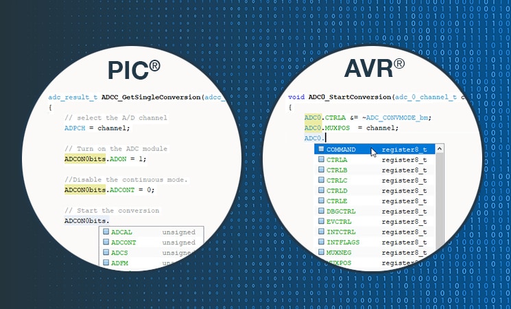
At Microchip, application engineers proficient at writing bare-metal code for either PIC or AVR MCUs did not naturally transition to the other seamlessly, relying initially on tools such as MCC or Atmel START. For my own part, working from Microchip’s Trondheim office in Norway (the home of AVR MCUs), I was much more confident using MCC for AVR MCUs, than I was for PIC MCUs. As I described above, one only becomes 100% comfortable with these tools when you can write the code that they generate yourself. Since I found writing basic bare-metal code for PIC MCUs quite challenging, this was to be expected. In addition, code completion only works once you know the patterns, so I was getting frustratingly little help when attempting to write register-level PIC MCU code.
Figure 3: Code completion help for starting an ADC conversion (for PIC and AVR MCUs); view Figure 3
The one classic application note which covered this topic was AVR1000: Getting Started Writing C Code for XMEGA. This was published in 2008 when extensions and improvements were made to both the (peripheral) module structure and header files of the then-new family of AVR MCUs, the XMEGA. These same conventions were internally applied to all new AVR MCU devices released since then. It may not have been obvious that this application note was still key, in terms of describing the patterns of writing C code for all new AVR MCU devices. In addition, some form of documentation was needed to help make sense of the differences between the register-level PIC and AVR MCU code.
To leverage existing experience on either AVR or PIC MCUs, two application notes were created. They were designed to be read side-by-side, so that a customer (or Microchip applications engineer) familiar with one of the architectures could easily pick up the differences between the two and more quickly get up and running with the other.
Let’s explore these symmetrical application notes, which have been designed to help make sense of the differences between low-level PIC and AVR MCU code:
● AVR1000b: Getting Started Writing C-code for AVR
● PIC1000: Getting Started Writing C-code for PIC16 and PIC18
The following sections give examples of what is covered in each of PIC1000 and AVR1000b application note chapters:
● Chapter 1: Datasheet module structure and naming conventions
● Chapter 2: Module representation in header files
● Chapter 3: Writing C-code for PIC and AVR MCUs (PIC1000 & AVR1000b)
● Chapter 4: Application Example Showing Alternative Ways of Writing Code
Chapter 1: Datasheet Module Structure and Naming Conventions (PIC1000 & AVR1000b)
At least part of the reason for why bare-metal coding proficiency does not easily translate from one MCU product family to another is that datasheet module organizational patterns often tend to be implicit and naming conventions often need to be deduced.
The first chapter of each attempts to remedy this by giving an explicit guide to the module organization and naming conventions.
Figure 4: Register naming conventions for PIC and AVR MCUs (extracts from PIC1000, AVR1000b); view Figure 4
For example, let’s consider the register naming conventions for AVR and PIC MCUs with respect to the ADC control registers.
Figure 5: Excerpt of ADC Register Summaries for AVR and PIC MCUs; view Figure 5
When working on MPLAB X IDE (or Atmel Studio 7), a useful working view of registers, bits and bit fields can be found using IO view. If you start a debug session, you will be able to manipulate the register bits directly, e.g. to turn on/off LEDs on your board.
Figure 6: Using IO View for to view module registers, bits and bitfields. In debug mode this status will be live and interactive; view Figure 6
Note: You are also able to use IO View as a more efficient way of using the datasheet, by selecting a register, then clicking the pdf icon. This opens the HTML version of the datasheet in the context of that register. This context help is supported for the latest PIC and AVR devices.
In addition, for AVR MCUs you are also able to navigate the HTML datasheet using the editor. This is done by selecting the PERIPHERAL.REGISTER then clicking the PDF datasheet icon, see Figure 7. Also see MPLAB® X - Context Datasheet Help & AVR® Interrupts (at 2min38).
Figure 7: Datasheet context help from IO View (and from the Editor for AVR); view Figure 7
Chapter 2: Module Representation in Header Files (PIC1000 & AVR1000b)
In this chapter you will find summaries of the various device header file definitions for both PIC and AVR MCUs, such as structs, unions and bit field masks. These definitions will determine what code completion help you will receive when writing code for the device. Using these definitions, your code will be more readable than simply assigning hex values to a register. Even if you comment your code, if the comments get out of date, you may have code which is very difficult to debug.
Let’s consider again the code completion examples used in Figure 1.
For a PIC MCU, the reason code completion options are given for the bits in the ADCON0 register is due to type definition of ADCON0bits_t, made up of struct and union bitfield definitions in the device header files.
For an AVR MCU, the reason why code completion suggests a list of registers in the ADC0 instance of the ADC module is due to definition of an ADC_t struct, comprising of all the registers in an ADC module.
Figure 8: Code Completion due bitfield definitions (PIC MCU) and ADC_t struct (AVR MCU) and in AVR/PIC MCU header files; view Figure 8
Note: The register names for an AVR MCU module are not unique, i.e. there may be several instances of an ADC module in an MCU, furthermore there may be more than one type of module which has a CTRLA register. So, for an AVR MCU, a register is only fully defined in the context of a specific module instance. However, a PIC MCU has both module and instance built into the register name, i.e. ADCON1.
Note: for AVR MCUs, there are module instance register definitions available as an option.
Figure 9: Module instance register definitions for an AVR MCU; view Figure 9
Chapter 3: Writing C-Code for PIC or AVR MCUs (PIC1000 & AVR1000b)
This chapter of the associated application notes covers some key use cases with regards to writing to device registers. Using the various constructs in device header file discussed in Chapter 2, recommendations of best practice for the following use cases are given:
● Set and Clear Register Bits
● Configure Register Bit Fields
● Update/Change Register Bit Fields
Note that updating a register is different from an initial configuration of that register when it is in a known state after device reset. Read-modify-write considerations need to be considered in order to only update the intended bits or bit fields.
In the example used in this article, the MCC-generated code was written as follows, however, several alternatives are possible.
Chapter 4: Application Example Showing Alternative Ways of Writing Code
In this chapter code listings are provided, for each of the alternative styles of writing register-level code. A simple application is used, configuring the pins then turning on a LED when a button is pressed. Code listings are then provided for each of the different coding styles supported, for both the PIC MCU and AVR MCU versions of the application note. These code listings may be a useful reference to facilitate code style discussions at your company. For example, if you are planning project which will use both PIC and AVR MCUs, then the bit mask or bit position style may allow fairly similar code between AVR and PIC MCUs.
Summary
These symmetric application notes, Writing C-Code for PIC/AVR (PIC1000 & AVR1000b), were written to help engineers more easily write readable register-level C code, achieved through:
Explicitly defining module patterns and naming conventions in the device datasheet
Describing the device header file structures and defines for each MCU module
Giving examples of best-practice coding style for accessing and manipulating registers
They should be useful whether you are coding from scratch, trying to better understand the code generated by MCC or Atmel START or looking to make an informed coding-style decision by weighing the options. In addition, used side by side, these application notes help make sense of the differences between low-level PIC and AVR MCU code.
Specifically, an attempt has been made to understand MCC-generated code as well as to make full use of MPLAB X IDE features such as code completion and IO view, in order to write easy-to-read, best practice C code. Many of these MPLAB X IDE features are demonstrated in the video: MPLAB® X - Context Datasheet Help & AVR® Interrupts, in the process of writing the bare-metal AVR code required to turn on an LED when a button is pressed.
So, if you’re used to writing bare metal code for either PIC or AVR MCUs, why not try getting the basics working on the other?
Download both application notes – and try reading them side by side to get a feeling for the differences between the MCU you’re familiar with and the new one. At the end of each, you will also find links to technical briefs, which give more bare-metal example code for a range of different peripherals.
● AVR1000b: Getting Started Writing C-code for AVR
● PIC1000: Getting Started Writing C-code for PIC16 and PIC18
I welcome your questions and thoughts, please connect with me on LinkedIn.