What Is Zero Cross Detect (ZCD)?
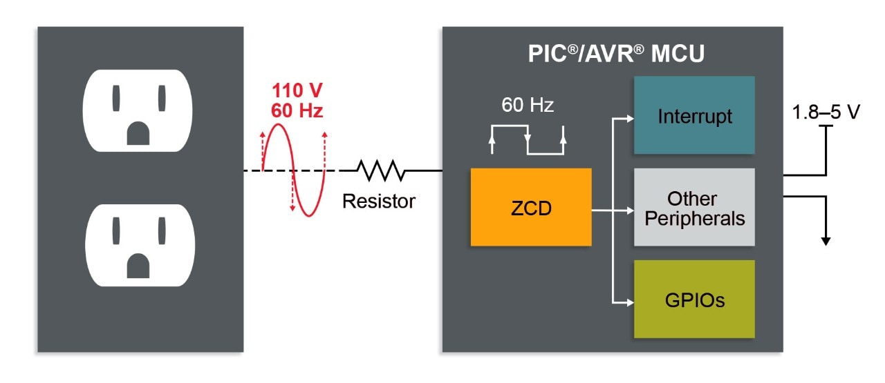
Zero Cross Detect (ZCD) detects when an Alternative Current (AC) signal crosses through the ground potential. The ZCD module is useful when monitoring an AC waveform for purposes such as TRIAC dimming, AC period measurement and minimizing EMI caused by switching transients.
How Can Your Design Benefit From an On-Chip ZCD?
If the microcontroller (MCU) you have selected doesn’t have an on-chip ZCD, you will need to build an external circuit with passive components. This will not only lead to higher power consumption and BOM costs, but it will also result in a current injection into the substrate, which may damage the MCU.
The on-chip ZCD peripheral in PIC® and AVR® MCUs can take the signal directly from the AC main with only a resistor or a capacitor in series. This saves BOM costs and reduces energy loss while also preventing substrate current injection.
The ZCD peripheral can be easily configured with MPLAB® Code Configurator (MCC) for PIC MCUs and Atmel START for AVR MCUs.

How Is ZCD Used?
ZCD Operating Circuit
To safely interface with the AC input signal, a current-limiting resistor (and/or capacitor in some cases) is needed in series with the input. The value of that resistor/capacitor is calculated based on the AC input voltage and the current specs of the ZCD peripheral. An optional pull-up or pull-down resistor can also be added to balance zero-crossing voltage offset.
ZCD Configuration and Output
The ZCD peripheral is very easy to configure. The ZCD output signal is a simple digital level that toggles from active low to high when the signal crosses from negative to positive or vice versa. The output signal can be used to trigger other peripherals internally, or output to a GPIO pin externally. You can also configure the peripheral to trigger an interrupt when the signal crosses positively, negatively, or both.
Zero Cross Detect (ZCD) in PIC and AVR MCUs
The AVR DA family of MCUs has a new feature not previously seen integrated in AVRs: The Zero Cross Detect (ZCD). This video explains what a ZCD is and why the new implementation is better than the traditional method of ZCD.

Zero Cross Detect (ZCD) in PIC and AVR MCUs
The AVR DA family of MCUs has a new feature not previously seen integrated in AVRs: The Zero Cross Detect (ZCD). This video explains what a ZCD is and why the new implementation is better than the traditional method of ZCD.

How to Use the Zero Cross Detect (ZCD) Peripheral on AVR®
How to Use the Zero Cross Detect (ZCD) Peripheral on AVR®
To avoid using potentially dangerous mains voltages, this demo uses the Digital to Analog Converter (DAC) to produce a sine wave.
This video is a follow-on from the previous ZCD video:
https://www.youtube.com/watch?v=Kxnyk1T-iFw&t=96s
Relevant Links:
TB3138: ZCD Module on PICs
https://ww1.microchip.com/downloads/en/Appnotes/90003138A.pdf
ZCD Design Center MCU8 Webpage
Atmel Studio 7 Design Center Page
https://ww1.microchip.com/downloads/en/DeviceDoc/Getting-Started-with-Atmel-Studio7.pdf
GITHUB TB3233 code example
https://github.com/microchip-pic-avr-examples/avr128da48-using-zcd-for-special-functions
TB3233 Using ZCD to implement special functions (and code example)
AVR DA Curiosity Nano family page
https://www.microchip.com/en-us/development-tool/dm164151
AVR128DA48 Product Page