Loading
Log in to myMicrochip to access tools and benefits. Sign up in just one minute.
Maximize Your Experience: Reap the Personalized Advantages by Completing Your Profile to Its Fullest. Update Here
Stay in the loop with the latest from Microchip. Update your profile while you are at it. Update Here
Complete your profile to access more resources. Update Here
What Is an Operational Amplifier?
An operational amplifier is a type of analog circuit that is designed to amplify the difference between the inputs non-inverting (positive) and inverting (negative) inputs. Operational amplifiers are commonly used to buffer or amplify signals, such as the signals from sensors, current shunts and resistive dividers. The Operational Amplifier (OPA) module on PIC® microcontrollers (MCUs) and the Analog Signal Conditioning (ASC) module on AVR® MCUs can feature internal resistor ladders that enable the peripheral to function as a Programmable Gain Amplifier (PGA), which increases the size of the signal to maximize the resolution in an Analog-to-Digital Converter (ADC).
Try a Live Operational Amplifier Demo
Are you an embedded application engineer starting your next design, and do you want to take advantage of an on-chip op amp? Do you find yourself looking for hands-on experience to understand how these features work in real time? Now, you can interact with physical demos on your screen from anywhere. Microchip Try is a website for visual learners that provides real-time demos you can interact with by changing variables and watching how the demo responds.

Embedded or Discrete Operational Amplifiers: Which Do You Need?
Embedded Operational Amplifiers
Embedded operational amplifiers are designed to be used as general-purpose operational amplifiers. A few of the common use cases that benefit from the peripheral are listed below:
- Denser system integration and lower BOM cost: The module is integrated with the MCU, which reduces the number of components used and saves board space
- Buffering the ADC input: The operational amplifier can be used to directly feed the ADC*, which can improve signal acquisition times
- Synergy with other analog peripherals: Other analog peripherals, such as the Digital-to-Analog Converter (DAC) and Analog Comparator, can be used in conjunction with the operational amplifier to unlock new uses for existing peripherals
Discrete Operational Amplifiers
Some demanding analog applications require a discrete operational amplifier. Here are some of the benefits that our wide array of discrete operational amplifiers offer:
- Bipolar power supply support: Discrete operational amplifiers are available in configurations that support bipolar power rails, enabling negative inputs and outputs
- Exceptional performance: Generally, discrete operational amplifiers have more area on the die, which improves analog performance across the board
- More output current: Discrete operational amplifiers can have larger output stages, which enables them to drive heavier loads
Features vary by device. Please consult the device data sheet for more information on the features and feature configurations available on each device.
Selectable Input Pins
Optimize and Simplify Layout
The pins associated with the operational amplifier module are multiplexed. This feature can be used to select a different pin that is farther away from switching logic to reduce the amount of crosstalk or it can be used to simplify PCB layout.
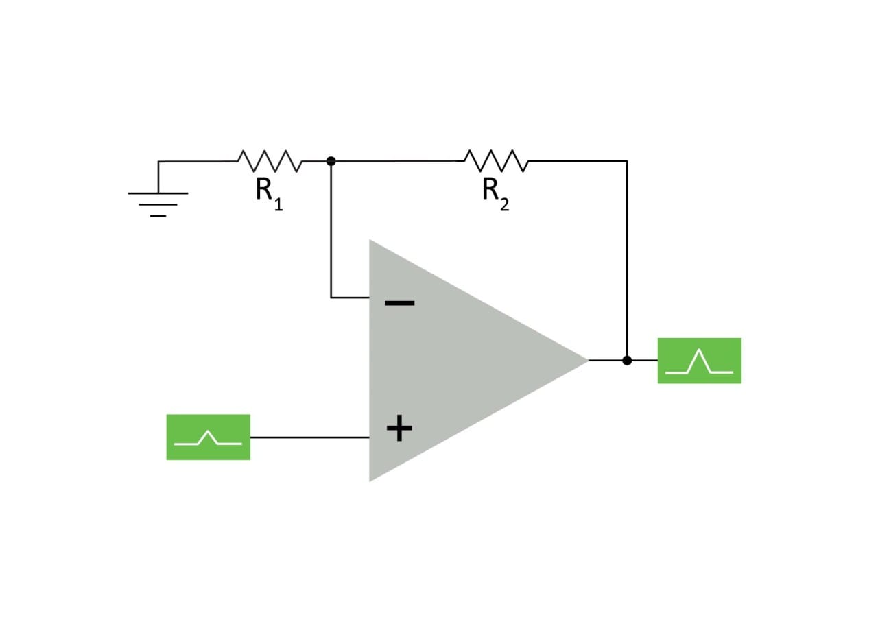
Internal Resistor Ladder
Reduce the BOM
The internal resistor ladder removes the need for external resistors for most configurations. The ladder can be used to select and switch between the desired gains. For applications requiring gains that are not available on the ladder—or those requiring a greater degree of accuracy—the ladder can be disabled, and external feedback resistors can be used instead.
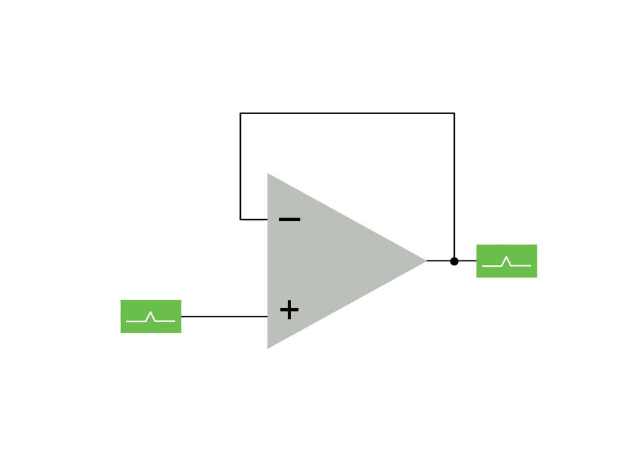
Internal Unity Gain Override
The internal unity gain override forces the operational amplifier into unity gain by shorting the output and the inverting input*. Some devices may leave the negative input pin still connected, enabling this feature to be used as a discharge route for an integration capacitor.
Controllable Charge Pump
The internal charge pump in the OPA module can be enabled for enhanced analog performance for demanding applications, however, this increases the OPA module’s current consumption.
Internal Connection to ADC
The ADC on the device can directly sample the output of the operational amplifier without an external jumper to another pin. The module can also be used as a buffer for the ADC, which can improve signal acquisition time and resolution.
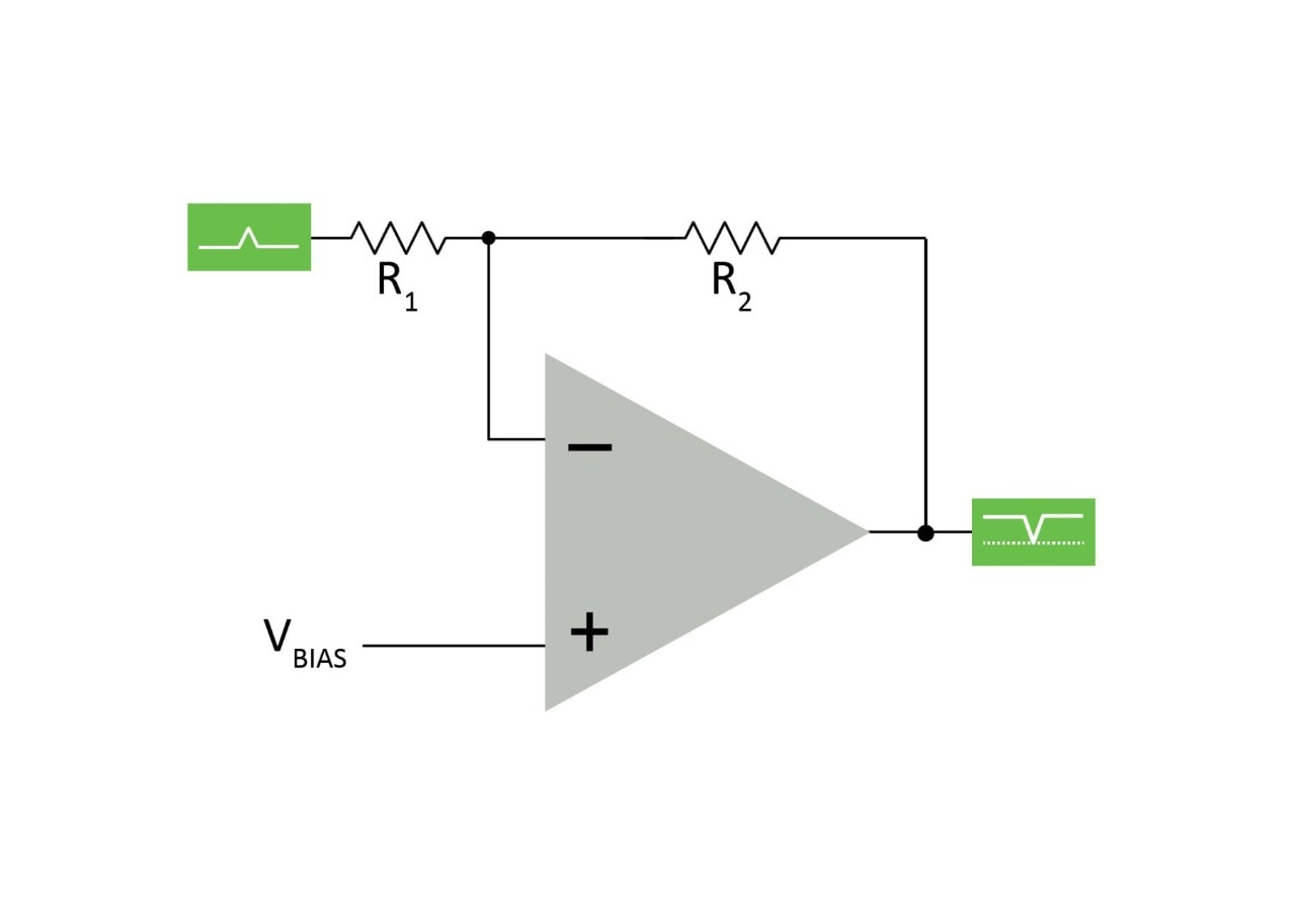
Input Offset Voltage Calibration Register
Each device is calibrated at the factory with a value that nulls the input offset voltage to within the specified data sheet tolerance. On some devices, this register can be overwritten at runtime for applications that contain a self-calibration routine. On a power-on reset, the factory value of the register is restored.
Software Override
The software override feature can be used to force the operational amplifier to a specific output, such as VDD, VSS, or tri-state*, while ignoring the inputs to the operational amplifier.
Tri-Stated Output
The output of the operational amplifier can be tri-stated, which allows for the creation of sample-and-hold circuits using the output and an external capacitor.
Hardware-Controlled Override
The hardware override can be used to switch the output configuration of the operational amplifier using an internal hardware signal, removing the need for core intervention.
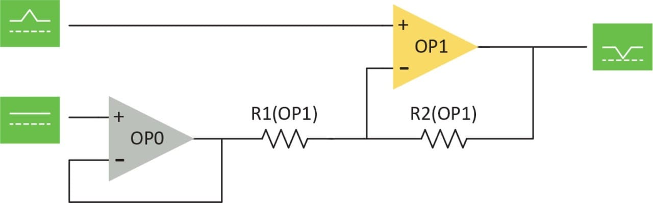
Internal Connections to Other Analog Peripherals
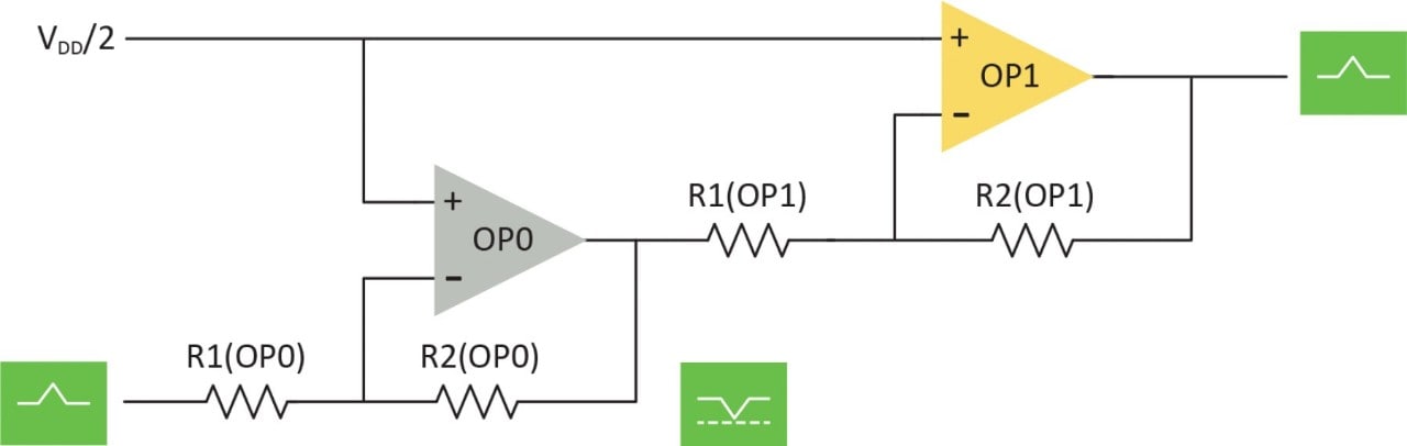
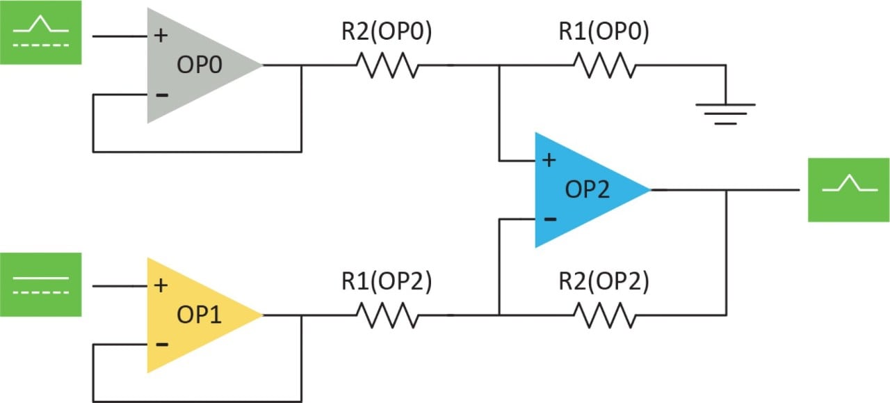
Other on-chip analog peripherals can be connected to the operational amplifier’s inputs*. This could be used to mirror (and/or track) the DAC, to output the Fixed Voltage Reference (FVR) for external devices, or to build a cascade of internal operational amplifiers for more signal bandwidth.
*Implementation varies by device. Consult the MCU family data sheet for more information.
MPLAB® Mindi™ Analog Simulator
MPLAB Mindi Analog Simulator uses a SIMetrix/SIMPLIS environment to model circuit behavior, reducing design time with software debugging for initial design verification.

|
Title
|
|
|---|---|
| Using the Operational Amplifier on PIC16 and PIC18 | Download |
| Optimizing Internal Operational Amplifiers for Analog Signal Conditioning | Download |
| Using the Internal OPAMP as Regulated Power Supply for MVIO | Download |
| Constant-Current Driver Using the Analog Signal Conditioning (OPAMP) Peripheral | Download |
| Gain and Offset Calibration of the Analog Signal Conditioning (OPAMP) Peripheral | Download |
| Getting Started with Analog Signal Conditioning (OPAMP) | Download |
| Low-BOM Microphone Interface Using the Analog Signal Conditioning (OPAMP) Peripheral | Download |
| Analog Sensor Measurement and Acquisition | Download |
What are Integrated OPAMPs?
This video is an overview of the integrated OPAMP peripheral on PIC and AVR microcontrollers and some of the common use cases.
