We detect you are using an unsupported browser. For the best experience, please visit the site using Chrome, Firefox, Safari, or Edge. X
Maximize Your Experience: Reap the Personalized Advantages by Completing Your Profile to Its Fullest! Update Here
Stay in the loop with the latest from Microchip! Update your profile while you are at it. Update Here
Complete your profile to access more resources.Update Here!
0
$0.00
Item Qty
Your cart is empty.

Solutions for Switched Reluctance (SR) Motor Control


A Switched Reluctance (SR) or variable reluctance motor does not contain any permanent magnets. The tradeoff for this low-cost construction is a more complex drive with more switches and complex control techniques to achieve a smooth torque operation. SR motors are ideal for applications that require high-speed operation and power density in a compact form factor.

Permanent Magnet-less Switched Reluctance Motor

Typical Applications


  • Fuel pumps
  • Throttle controls
  • Oil pumps
  • Anti-Lock Braking Systems (ABS)
  • Vacuum cleaners
Products Sensored Field Oriented Control Sensorless Field Oriented Control
Microcontrollers (MCUs),
Digital Signal Controllers (DSCs) and
Field-Programmable Gate Arrays (FPGAs)
dsPIC33 DSCs
32-bit PIC32MK and SAM MCUs
IGLOO® 2 FPGAs
SmartFusion® 2 SoC FPGAs
dsPIC33 DSCs
32-bit PIC32MK and SAM MCUs
IGLOO 2 FPGAs
SmartFusion 2 SoC FPGAs
3-Phase Gate Drivers ATA6843
ATA6844
MIC4604
MIC4605
ATA6843
ATA6844
MIC4604
MIC4605

Some Basics About Switched Reluctance (SR) Motors


How a SR Motor Works

While SR motor control is simple to implement, this type of motor is not commonly available. The stator is similar to that of a Brushless DC (BDC) motor, however, the rotor is made only of iron laminates. The iron rotor is attracted to the energized stator pole, and the polarity of the stator pole does not matter. Torque is produced as a result of the attraction between the electromagnet and the iron rotor.

SR Motor Characteristics

  • Synchronous operation
  • Low-cost motor due to simple and magnet-free construction
  • More suitable for high-speed/power density applications
Switched Reluctance Motor Segment Diagram

Implementing SR Motor Control


How It Works


The simple, inexpensive construction of a SR motor requires a microcontroller for speed control and to reduce torque ripple and audible noise. The rotor forms a magnetic circuit with the energized stator pole. The reluctance of this magnetic circuit is the magnetic equivalent of the resistance of an electric circuit. The reluctance of the magnetic circuit decreases as the rotor aligns with the stator pole. When the rotor is in line with the stator, the gap between the rotor and stator is very small. At this point, the reluctance is at its minimum. This is where the name Switched Reluctance comes from; the inductance of the energized winding also varies as the rotor rotates. When the rotor is out of alignment, the inductance is very low and the current will increase rapidly. When the rotor is aligned with the stator, the inductance will be very large and the current decreases slowly this results in  torque rippleThis is one of the difficulties in driving a switched reluctance motor.

Microcontroller Features for SR Motor Control


Basic I/O Digital/analog signal for speed direction and torque
Capture/Compare/Pulse-Width Modulation (CCP) Generate independent PWMs for multiple MOSFET switches and tachometer input for speed sensing using input capture
Comparators Overcurrent detection and protection
Analog-to-Digital Converter (ADC) Measurement of phase current and DC bus voltage for speed and position sensing in sensorless control
Quadrature Encoding Interface (QEI) Optical encoder interfacing for position sensing
Communication Peripherals (I2C, SPI, CAN) Typically torque, speed, position and/or direction

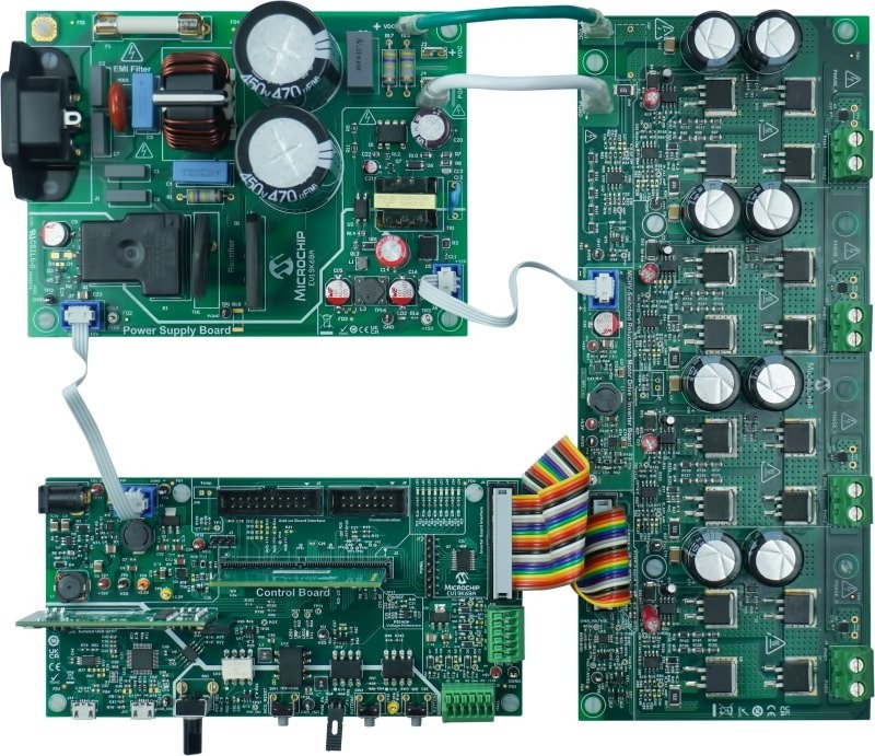
Motor Control Hardware and Software Solutions


Featured Software Tools


Motor Control Application Algorithm and Software Library

Motor Control Application Algorithm and Software Library

To support the development of motor applications, we provide Brushed DC motor control examples.

MPLAB X IDE Logo

MPLAB® X Integrated Development Environment (IDE)

MPLAB X Integrated Development Environment (IDE) is an expandable, highly configurable software program that incorporates powerful tools to help you discover, configure, develop, debug and qualify embedded designs for Microchip’s microcontrollers and digital signal controllers.

MPLAB Code Configurator Logo

MPLAB Code Configurator (MCC)

MPLAB Code Configurator (MCC) is a free, graphical programming environment that generates seamless, easy-to-understand C code to be inserted into your project.

Products


Documentation


Title
Sensorless Field Oriented Control (FOC) of an AC Induction Motor (ACIM) Using Field Weakening Download
Sensorless Position Control of Brushed DC Motor Using Ripple Counting Technique Download
Integrated Power Factor Correction (PFC) and Sensorless Field Oriented Control (FOC) System for Microchip 32-bit Microcontrollers Application Note Download
Sensorless Field Oriented Control (FOC) of an AC Induction Motor (ACIM) Download
AC Induction Motor Fundamentals Download
VF Control of 3-Phase Induction Motor Using Space Vector Modulation Download
Sensorless 3-Phase Brushless Motor Control with the PIC16FXXX Download
Controlling 3-Phase AC Induction Motors Using the PIC18F4431 Download
Brushed DC Motor Fundamentals Download
Sensored (Encoder-Based) Field Oriented Control of a Three Phase Permanent Magnet Synchronous Motor (PMSM) Download
Sensorless Field Oriented Control (FOC) for a Permanent Magnet Synchronous Motor (PMSM) Using a PLL Estimator and Equation-based Flux Weakening (FW) Application Note Download
An Introduction to AC Induction Motor Control Using the dsPIC30F / dsPIC33F DSC Download
Bidirectional VF Control of Single and 3-Phase Induction Motors Using the PIC16F72 Download
VF Control of 3-Phase Induction Motors Using PIC16F7X7 Microcontrollers Download
Sensorless Field Oriented Control (FOC) for a Permanent Magnet Synchronous Motor (PMSM) Using a PLL Estimator and Field Weakening (FW) Download
Field Oriented Control of a Three-Phase BLDC Motor using a Rotary Inductive Position Sensor Download
Title
CE002 Configuring 10-Bit dsPIC DSC A/D Converters for 1 Msps Conversion Rate Download
CE019 - Proportional Integral Derivative (PID) controllers & closed-loop control Download
Sensorless FOC PLL Estimator MCLV Download
PFC Sensorless FOC PLL Estimator MCHV Download
CE155 - Real-Time Data Monitoring (RTDM) Example Download
Title
dsPIC33 Motor Control Library for FOC Download
Title
dsPICDEM MCLV-2 (DM330021-2) Development Board User's Guide Download
dsPICDEM MCSM Development Board Users Guide Download
Motor Control Starter Kit with mTouch User Guide Download
dsPICDEM MCHV-2 Development Board User's Guide Download
Title
WP100 - How to Turn an AC Induction Motor Into a DC Motor (A Matter of Perspective) Download

Title

Lorem ipsum dolor sit amet, consectetur adipiscing elit. Vestibulum vehicula velit sit amet turpis rutrum vehicula. Donec eu varius velit, nec ultricies arcu. Fusce vitae pulvinar lorem. Etiam sodales et ipsum volutpat suscipit. Aliquam non mauris ut lectus volutpat feugiat id eget massa. Aliquam vel eleifend metus. Nam ultricies, risus sed tempor suscipit, dolor ligula sodales erat, et porta magna sem fermentum felis. Orci varius natoque penatibus et magnis dis parturient montes, nascetur ridiculus mus. Donec commodo magna at scelerisque sollicitudin. Morbi elit tortor, blandit vel imperdiet in, ullamcorper eu tortor. Etiam dapibus eleifend elementum. Vestibulum finibus efficitur mauris, vitae convallis ex molestie non. Etiam luctus at mauris accumsan finibus.