Loading
Log in to myMicrochip to access tools and benefits. Sign up in just one minute.
Maximize Your Experience: Reap the Personalized Advantages by Completing Your Profile to Its Fullest. Update Here
Stay in the loop with the latest from Microchip. Update your profile while you are at it. Update Here
Complete your profile to access more resources. Update Here
true
Traditionally, logic gates are external components used to implement simple logic functions, such as ANDing multiple signals into a single good/bad signal. Logic gates can operate independently of the CPU for fast response time. The custom logic peripherals on PIC® and AVR® microcontrollers (MCUs) integrate this functionality into the die of the MCU, removing these external components from the Bill of Materials (BOM).

Custom Logic on PIC and AVR MCUs
What is the CLB?
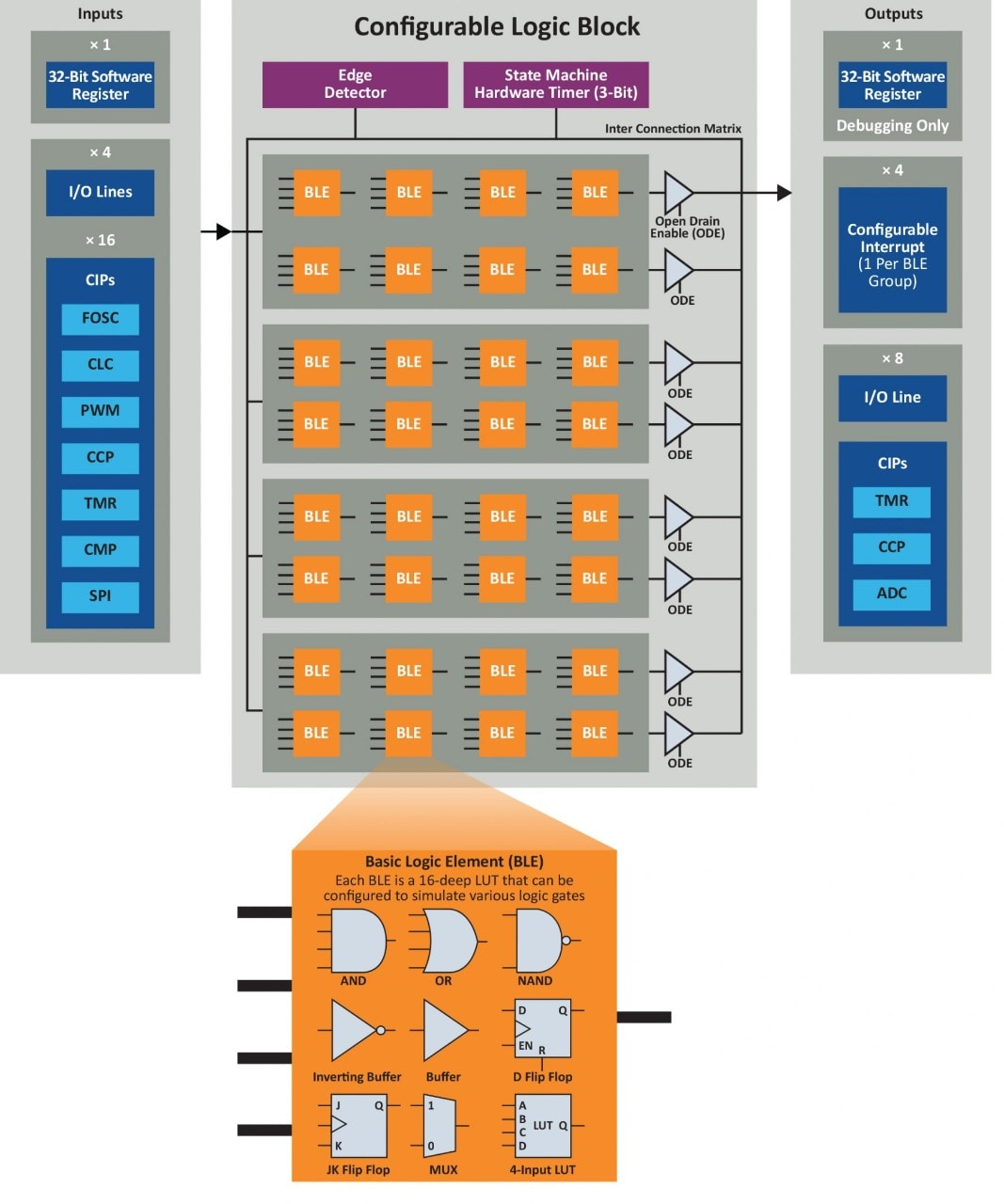
The Configurable Logic Block (CLB) is an on-chip array of Lookup Tables (LUTs) within a single peripheral. The array shares a common clock source and can drive I/O pins directly through Peripheral Pin Select (PPS) with support for tri-state. The CLB can be configured through our CLB Synthesizer tool.
What is the CLC or CCL?
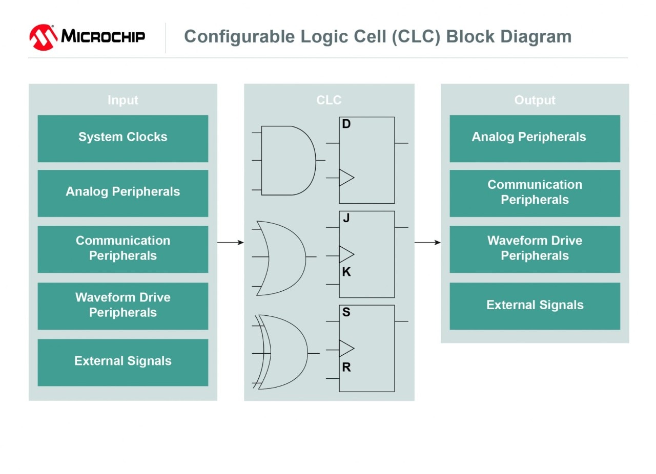
The on-chip Configurable Logic Cell (CLC) peripheral on PIC MCUs and Configurable Custom Logic (CCL) peripheral on AVR MCUs act like a configurable logic gate with the ability to operate in configurations such as AND/OR/XOR/1-input D flip-flop and more. Our MPLAB® Code Configurator (MCC) can easily reconfigure the gate(s) using a graphical interface.
How Can Your Design Benefit?
With custom logic peripherals, you can apply combinatorial and sequential logic to both internal and external signals. This bypasses the CPU through hardware-based logic and automates task handling within your system.
How Are They Used?
Configurable Logic Cell on PIC MCUs
The CLC has a variety of basic gates as well as sequential logic options that can be customized to create the logic specific to your application. With these logic gates, the CLC gives you the ability to combine signals to make a new custom signal without running code to execute it. This peripheral can also be used for routing pins on the MCU. For instance, you can easily configure the CLC peripheral to route the incoming RX signal of a connected Bluetooth® module to the virtual TX pin of your development board.
Configurable Custom Logic on AVR MCUs
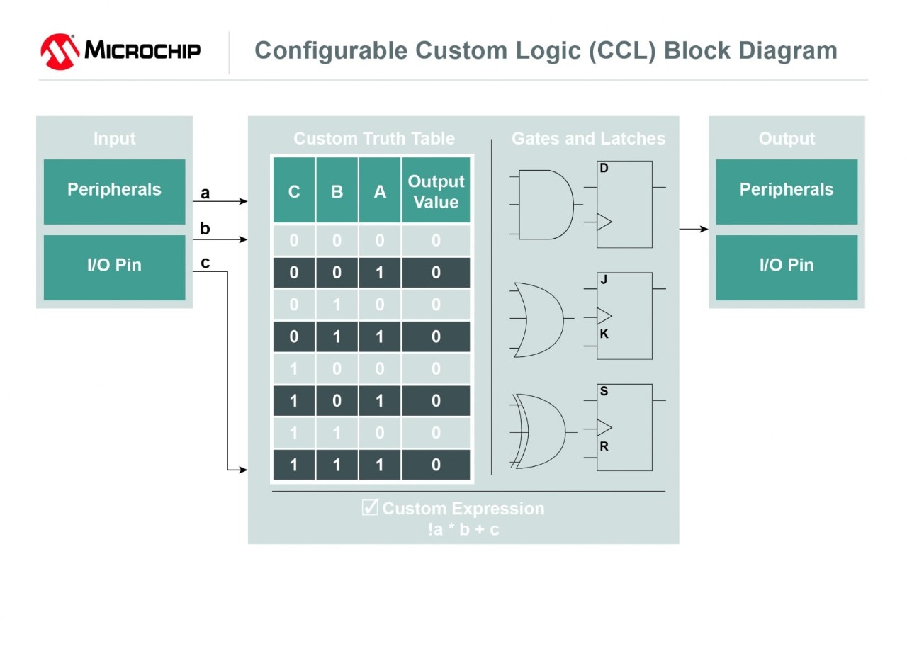
The CCL on AVR MCUs can function as a simple logic gate, flip-flop, delay element, filter or latch. You can also build your own custom gates through the lookup table. The lookup table behaves like a programmable truth table and features the ability to set the output of your gate based on entered values or an entered expression such as (!a * b + c). The results of the CCL can be used to trigger other peripherals as well without any CPU intervention.
Application Notes
|
Title
|
|
|---|---|
| Using CLCs in Real-Time Applications | Download |
| Core Independent Brushless DC Fan Control Using CCL AVR Microcontrollers | Download |
| Using the Configurable Logic Cell (CLC) to Interface a PIC16F1509 and WS2811 LED Driver | Download |
| Core Independent Nightlight Using Configurable Custom Logic on ATtiny1617 | Download |
| Configurable Logic Cell on PIC Microcontrollers | Download |
| Extending PIC MCU Capabilities Using CLC | Download |
8-bit Microcontrollers With Custom Logic Peripherals
- CLB MCUs
- CLC MCUs
- CCL MCUs
Similar Devices
Loading
Similar Devices
Loading